
User manual


PDx-113-57/60-SE / TMCM-113-57/60-SE Firmware Manual (V1.10 / 2009-OCT-28) 81
Copyright © 2009, TRINAMIC Motion Control GmbH & Co. KG
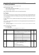
Number
Axis Parameter
Description
Range [Unit]
Access
143
max. current at rest
In contrast to the standby current, this current limit
becomes immediately active when the motor speed
reaches zero. The value represents a fraction of the
absolute maximum current:
0 – no change of current at rest (default, 100%)
1…7 – 12.5% …87.5%
See the TMC428 datasheet for details. Normally not
used, use parameters 6 and 7 instead!
0…7
RWE
144
max. current at low
accel.
An optional current reduction factor, see
parameters 136 and 143 for details. Normally not
used, use parameters 6 and 7 instead!
0…7
RWE
145
max. current at high
accel.
An optional current reduction factor, see
parameters 136 and 143 for details. Normally not
used, use parameters 6 and 7 instead!
0…7
RWE
146
acceleration factor
A ramping parameter, can be adjusted in special
cases, automatically calculated by setting the
maximum acceleration (e.g. during normal
initialization). See the TMC428 data sheet for
details. Normally no need to change.
0…128
RWE
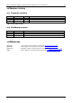
149
soft stop flag
If cleared, the motor will stop immediately
(disregarding motor limits), when the reference or
limit switch is hit.
0/1
RWE
151
position latch flag
Indicates that a position snapshot has been
completed (see parameter 142).
0/1
R
153
ramp divisor
The exponent of the scaling factor for the ramp
generator- should be de/incremented carefully (in
steps of one).
0…13
RWE
154
pulse divisor
The exponent of the scaling factor for the pulse
(step) generator – should be de/incremented
carefully (in steps of one).
0…13
RWE
193
referencing mode
1 – Only the left reference switch is searched.
2 – The right switch is searched, and then the left
switch is searched.
3 – Three-switch-mode: the right switch is searched
first, and then the reference switch will be
searched.
1/2/3
RWE
194
referencing search
speed
For the reference search this value specifies the
search speed as a fraction of the maximum
velocity:
0 – full speed
1 – half of the maximum speed
2 – a quarter of the maximum speed
3 – 1/8 of the maximum speed (etc.)
0…8
RWE
195
referencing switch
speed
Similar to parameter no. 194, the speed for the
switching point calibration can be selected.
0..8
RWE
203
mixed decay
threshold
If the actual velocity is above this threshold, mixed
decay will be used. This can also be set to –1
which turns on mixed decay permanently also in
the rising part of the microstep wave. This can be
used to fix microstep errors.
0..2048
or -1
16MHz
65536
2
PD
steps
sec
RWE
204
freewheeling
Time after which the power to the motor will be
cut when its velocity has reached zero
0..65535
0 = never
[msec]
RWE