
User manual


PDx-113-57/60-SE / TMCM-113-57/60-SE Firmware Manual (V1.10 / 2009-OCT-28) 30
Copyright © 2009, TRINAMIC Motion Control GmbH & Co. KG
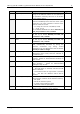
Number
Axis Parameter
Description
Range
9
ref. switch status
The logical state of the reference (left) switch.
See the TMC 428 data sheet for the different switch
modes. Default is two switch modes: the left switch as
the reference switch, the right switch as a limit (stop)
switch.
0/1
10
right limit switch status
The logical state of the (right) limit switch.
0/1
11
left limit switch status
The logical state of the left limit switch (in three switch
mode)
0/1
12
right limit switch disable
if set, deactivates the stop function of the right switch
0/1
13
left limit switch disable
Deactivates the stop function of the left switch resp.
reference switch if set.
0/1
130
minimum speed
Should always be set 1 to ensure exact reaching of the
target position. Do not change!
0... 2047
135
actual acceleration
The current acceleration (read only).
0... 2047
136
acceleration threshold
Specifies the threshold between low and high
acceleration values for the parameters 144 and 145.
Normally not needed.
0... 2047
137
acceleration divisor
A ramping parameter, can be adjusted in special cases,
automatically calculated by setting the maximum
acceleration (e.g. during normal initialization). See the
TMC428 data sheet for details. Normally no need to
change.
0…13
138
ramp mode
Automatically set when using ROR, ROL, MST and MVP.
0: position mode. Steps are generated, when the
parameters actual position and target position differ.
Trapezoidal speed ramps are provided.
2: velocity mode. The motor will run continuously and
the speed will be changed with constant (maximum)
acceleration, if the parameter "target speed" is changed.
For special purposes, the soft mode (value 1) with
exponential decrease of speed can be selected.
0/1/2
140
microstep resolution
0 – full step *)
1 – half step *)
2 – 4 microsteps
3 – 8 microsteps
4 – 16 microsteps
5 - 32 microsteps**)
6 – 64 microsteps**)
Modifying this parameter effects the rotation speed in
the same relation:
*) The full-step setting and the half-step setting are not
optimized for use without an adapted microstepping
table. These settings just step through the microstep
table in steps of 64 respectively 32. To get real full
stepping use axis parameter 211 or load an adapted
microstepping table.
**) If the module is specified for 16 microsteps only,
switching to 32 or 64 microsteps brings an enhancement
in resolution and smoothness. The position counter will
use the full resolution, but, however, the motor will
resolve a maximum of 24 different microsteps only for
the 32 or 64 microstep units.
0…6