PDx-113-57/60-SE TMCM-113-57/60-SE TMCLTM Firmware Manual Version: 1.10 2009-OCT-28 Trinamic Motion Control GmbH & Co KG Sternstraße 67 D – 20 357 Hamburg, Germany Phone +49-40-51 48 06 - 0 FAX: +49-40-51 48 06 - 60 http://www.trinamic.
PDx-113-57/60-SE / TMCM-113-57/60-SE Firmware Manual (V1.10 / 2009-OCT-28) Table of contents 1 2 3 4 5 Life support policy ....................................................................................................................................................... 4 Features ........................................................................................................................................................................... 5 Order codes ......................................
PDx-113-57/60-SE / TMCM-113-57/60-SE Firmware Manual (V1.10 / 2009-OCT-28) 6.7.31 Customer specific TMCLTM command extension (UF0…UF7/user function) ................................... 74 6.7.32 Request target position reached event ................................................................................................. 75 6.7.33 BIN (return to binary mode) .................................................................................................................... 76 6.7.
PDx-113-57/60-SE / TMCM-113-57/60-SE Firmware Manual (V1.10 / 2009-OCT-28) 1 Life support policy TRINAMIC Motion Control GmbH & Co. KG does not authorize or warrant any of its products for use in life support systems, without the specific written consent of TRINAMIC Motion Control GmbH & Co. KG.
PDx-113-57/60-SE / TMCM-113-57/60-SE Firmware Manual (V1.10 / 2009-OCT-28) 5 2 Features The PDx-113-57/60-SE is a full mechatronic device consisting of a NEMA 23 (flange size 57mm) or NEMA 24 (flange size 60mm) stepper motor, controller/driver electronics and integrated encoder. The electronics itself is also available without the motor as TMCM-113-57/60-SE module.
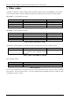
PDx-113-57/60-SE / TMCM-113-57/60-SE Firmware Manual (V1.10 / 2009-OCT-28) 6 3 Order codes The PDx-113-57/60-SE is currently available with two different stepper motor series (NEMA23 / 57mm flange size or) with four stepper motors of different length and holding torque each and two interface options: With NEMA 23 / 57mm flange size motor: Order code PD1-113-57-SE-option PD2-113-57-SE-option PD3-113-57-SE-option PD4-113-57-SE-option Description PANdrive with PANdrive with PANdrive with PANdrive with 0.
PDx-113-57/60-SE / TMCM-113-57/60-SE Firmware Manual (V1.10 / 2009-OCT-28) 7 4 Overview As with most TRINAMIC modules the software running on the microprocessor of the PDx-113-57/60-SE consists of two parts, a boot loader and the firmware itself. Whereas the boot loader is installed during production and testing at TRINAMIC and remains – normally – untouched throughout the whole lifetime, the firmware can be updated by the user.
PDx-113-57/60-SE / TMCM-113-57/60-SE Firmware Manual (V1.10 / 2009-OCT-28) 5 Putting the PDx-113-57/60-SE into operation Here you can find basic information for putting your PANdrive into operation. The text contains a simple example for a TMCLTM program and a short description of operating the module in direct mode.
PDx-113-57/60-SE / TMCM-113-57/60-SE Firmware Manual (V1.10 / 2009-OCT-28) 9 5.1 Starting up Here we show you, how to connect the RS232 interface. Use the RS485 interface similarly please. 1. Connect the interface: Please keep in mind that the RS232 transmit signal wire of the master has to be connected to the RS232 receive signal wire of the board and vice versa. PC (D-SUB 9pin) Pin 2 2.
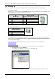
PDx-113-57/60-SE / TMCM-113-57/60-SE Firmware Manual (V1.10 / 2009-OCT-28) 5.2 Writing a simple TMCLTM program 1. Type the following text in the open window. //A simple example for using TMCL and the TMCL-IDE SAP 4, 0, 1000 //Set the maximum speed Loop: MVP ABS, 0, 150000 WAIT POS, 0, 0 WAIT TICKS, 0, 200 MVP ABS, 0, 0 WAIT POS, 0, 0 WAIT TICKS, 0, 100 JA Loop //Move to position 150000 //Move back to position 0 // Infinite Loop Assemble Stop Download 2. 3. 4. 5. Run Click the Assemble icon.
PDx-113-57/60-SE / TMCM-113-57/60-SE Firmware Manual (V1.10 / 2009-OCT-28) 11 5.3 Operating the module in direct mode 1. Start TMCL Direct Mode. Direct Mode 2. If the communication is established the TMCM-113-57/60-SE is automatically detected. If the module is not detected, please check all points above (cables, interface, power supply, COM port, baud rate). 3. Issue a command by choosing instruction, type (if necessary), motor, and value and click Execute to send it to the module.
PDx-113-57/60-SE / TMCM-113-57/60-SE Firmware Manual (V1.10 / 2009-OCT-28) 12 6 TMCLTM and TMCL-IDE The PDx-113-57/60-SE supports TMCLTM direct mode (binary commands or ASCII interface) and stand-alone TMCLTM program execution. You can store up to 2048 TMCLTM instructions on it. In direct mode the TMCLTM communication over RS485 or RS232 follows a strict master/slave relationship. That is, a host computer (e.g. PC/PLC) acting as the interface bus master will send a command to the PDx113-57/60-SE.
PDx-113-57/60-SE / TMCM-113-57/60-SE Firmware Manual (V1.10 / 2009-OCT-28) 13 Checksum calculation As mentioned above, the checksum is calculated by adding up all bytes (including the module address byte) using an 8-bit addition.
PDx-113-57/60-SE / TMCM-113-57/60-SE Firmware Manual (V1.10 / 2009-OCT-28) 14 6.2.1 Status codes The reply contains a status code. The status code can have one of the following values: Code 100 101 1 2 3 4 5 6 Meaning Successfully executed, no error Command loaded into TMCLTM program EEPROM Wrong checksum Invalid command Wrong type Invalid value Configuration EEPROM locked Command not available 6.3 Stand-alone applications The module is equipped with an EEPROM for storing TMCLTM applications.
PDx-113-57/60-SE / TMCM-113-57/60-SE Firmware Manual (V1.10 / 2009-OCT-28) 15 6.4.2 Parameter commands These commands are used to set, read and store axis parameters or global parameters. Axis parameters can be set independently for the axis, whereas global parameters control the behavior of the module itself. These commands can also be used in direct mode and in stand-alone mode.
PDx-113-57/60-SE / TMCM-113-57/60-SE Firmware Manual (V1.10 / 2009-OCT-28) 16 For calculating purposes there is an accumulator (or accu or A register) and an X register. When executed in a TMCLTM program (in stand-alone mode), all TMCLTM commands that read a value store the result in the accumulator. The X register can be used as an additional memory when doing calculations. It can be loaded from the accumulator.
PDx-113-57/60-SE / TMCM-113-57/60-SE Firmware Manual (V1.
PDx-113-57/60-SE / TMCM-113-57/60-SE Firmware Manual (V1.10 / 2009-OCT-28) 18 6.6 The ASCII interface TMCLTM also offers an ASCII interface that can be used to communicate with the module and to send some commands as text strings. The ASCII command line interface is entered by sending the binary command 139 (enter ASCII mode). Afterwards the commands are entered like in the TMCL-IDE. Please note that only those commands, which can be used in direct mode, also can be entered in ASCII mode.
PDx-113-57/60-SE / TMCM-113-57/60-SE Firmware Manual (V1.10 / 2009-OCT-28) 19 this case every character that is entered is echoed back when the module is addressed. A Character can also be erased using the backspace character (press the backspace key in a terminal program). When bit 4 is set and bit 5 is clear the characters that are entered are not echoed back immediately but the entire line will be echoed back after the character has been sent.
PDx-113-57/60-SE / TMCM-113-57/60-SE Firmware Manual (V1.10 / 2009-OCT-28) 20 6.7 Commands The module specific commands are explained in more detail on the following pages. They are listed according to their command number. 6.7.1 ROR (rotate right) With this command the motor will be instructed to rotate with a specified velocity in right direction (increasing the position counter). Internal function: First, velocity mode is selected.
PDx-113-57/60-SE / TMCM-113-57/60-SE Firmware Manual (V1.10 / 2009-OCT-28) 21 6.7.2 ROL (rotate left) With this command the motor will be instructed to rotate with a specified velocity (opposite direction compared to ROR, decreasing the position counter). Internal function: First, velocity mode is selected. Then, the velocity value is transferred to axis parameter #0 (target velocity). The module is based on the TMC428 motor controller and the TMC249 power driver.
PDx-113-57/60-SE / TMCM-113-57/60-SE Firmware Manual (V1.10 / 2009-OCT-28) 22 6.7.3 MST (motor stop) With this command the motor will be instructed to stop with deceleration ramp (soft stop). For information about hard stops refer to chapter 9 (hints and tips) please. Internal function: The axis parameter target velocity is set to zero. Related commands: ROL, ROR, SAP, GAP Mnemonic: MST 0 Binary representation: INSTRUCTION NO.
PDx-113-57/60-SE / TMCM-113-57/60-SE Firmware Manual (V1.10 / 2009-OCT-28) 23 6.7.4 MVP (move to position) With this command the motor will be instructed to move to a specified relative or absolute position or a pre-programmed coordinate. It will use the acceleration/deceleration ramp and the positioning speed programmed into the unit. This command is non-blocking – that is, a reply will be sent immediately after command interpretation and initialization of the motion controller.
PDx-113-57/60-SE / TMCM-113-57/60-SE Firmware Manual (V1.10 / 2009-OCT-28) 24 Example: Move motor to previously stored coordinate #8 Mnemonic: MVP COORD, 0, 8 Binary: Byte Index Function Value (hex) 0 1 Target- Instruction address Number $01 $04 2 Type $02 3 Motor/ Bank $00 4 Operand Byte3 $00 5 Operand Byte2 $00 6 Operand Byte1 $00 7 Operand Byte0 $08 8 Checksum $11 When moving to a coordinate, the coordinate has to be set properly in advance with the help of SCO or CCO.
PDx-113-57/60-SE / TMCM-113-57/60-SE Firmware Manual (V1.10 / 2009-OCT-28) 25 6.7.5 SAP (set axis parameter) With this command most of the motion control parameters of the module can be specified. The settings will be stored in SRAM and therefore are volatile. That is, information will be lost after power off. Please use command STAP (store axis parameter) in order to store any setting permanently. Internal function: The parameter format is converted ignoring leading zeros (or ones for negative values).
PDx-113-57/60-SE / TMCM-113-57/60-SE Firmware Manual (V1.10 / 2009-OCT-28) Number 7 Axis Parameter standby current 12 right limit switch disable 13 left limit switch disable 130 minimum speed 136 acceleration threshold 137 acceleration divisor 138 ramp mode 140 microstep resolution 141 ref. switch tolerance Description The current limit two seconds after the motor has stopped. if set, deactivates the stop function of the right switch Deactivates the stop function of the left switch resp.
PDx-113-57/60-SE / TMCM-113-57/60-SE Firmware Manual (V1.10 / 2009-OCT-28) Number 142 143 144 145 146 149 153 154 193 194 195 Axis Parameter snapshot position Description For referencing purposes, the exact position at hitting of the reference switch can be captured in this parameter. A dummy value has to be written first to prepare caption. max. current at rest In contrast to the standby current, this current limit becomes immediately active when the motor speed reaches zero.
PDx-113-57/60-SE / TMCM-113-57/60-SE Firmware Manual (V1.10 / 2009-OCT-28) Number 203 Axis Parameter mixed decay threshold 204 freewheeling 205 Stall Detection Threshold 209 210 Encoder Position encoder prescaler 211 Fullstep Threshold 214 power down delay 28 Description If the actual velocity is above this threshold, mixed decay will be used. This can also be set to –1 which turns on mixed decay permanently also in the rising part of the microstep wave.
PDx-113-57/60-SE / TMCM-113-57/60-SE Firmware Manual (V1.10 / 2009-OCT-28) 29 6.7.6 GAP (get axis parameter) Most parameters of the PDX-113-57/60-SE can be adjusted individually for the axis. With this parameter they can be read out. In stand-alone mode the requested value is also transferred to the accumulator register for further processing purposes (such as conditioned jumps). In direct mode the value read is only put out in the value field of the reply (without affecting the accumulator).
PDx-113-57/60-SE / TMCM-113-57/60-SE Firmware Manual (V1.10 / 2009-OCT-28) Number 9 Axis Parameter ref. switch status 10 11 right limit switch status left limit switch status 12 13 right limit switch disable left limit switch disable 130 minimum speed 135 136 actual acceleration acceleration threshold 137 acceleration divisor 138 ramp mode 140 microstep resolution Description The logical state of the reference (left) switch. See the TMC 428 data sheet for the different switch modes.
PDx-113-57/60-SE / TMCM-113-57/60-SE Firmware Manual (V1.10 / 2009-OCT-28) Number 141 142 143 144 145 146 149 151 153 154 193 194 195 Axis Parameter ref. switch tolerance Description For three-switch mode: a position range, where an additional switch (connected to the REFL input) won't cause motor stop. snapshot position For referencing purposes, the exact position at hitting of the reference switch can be captured in this parameter. A dummy value has to be written first to prepare caption.
PDx-113-57/60-SE / TMCM-113-57/60-SE Firmware Manual (V1.10 / 2009-OCT-28) Number 203 Axis Parameter mixed decay threshold 204 freewheeling 205 Stall Detection Threshold 206 208 209 210 Actual Load Value driver error flags Encoder Position encoder prescaler 211 Fullstep Threshold 214 power down delay 215 absolute encoder value Description If the actual velocity is above this threshold, mixed decay will be used.
PDx-113-57/60-SE / TMCM-113-57/60-SE Firmware Manual (V1.10 / 2009-OCT-28) 33 6.7.7 STAP (store axis parameter) An axis parameter previously set with a Set Axis Parameter command (SAP) will be stored permanent. Most parameters are automatically restored after power up. Internal function: An axis parameter value stored in SRAM will be transferred to EEPROM and loaded from EEPORM after next power up.
PDx-113-57/60-SE / TMCM-113-57/60-SE Firmware Manual (V1.10 / 2009-OCT-28) Number 137 138 140 143 144 145 Axis Parameter acceleration divisor Description A ramping parameter, can be adjusted in special cases, automatically calculated by setting the maximum acceleration (e.g. during normal initialization). See the TMC428 data sheet for details. Normally no need to change. ramp mode Automatically set when using ROR, ROL, MST and MVP. 0: position mode.
PDx-113-57/60-SE / TMCM-113-57/60-SE Firmware Manual (V1.
PDx-113-57/60-SE / TMCM-113-57/60-SE Firmware Manual (V1.10 / 2009-OCT-28) Number 214 Axis Parameter power down delay 36 Description Standstill period before the current is changed down to standby current. The standard value is 200msec.
PDx-113-57/60-SE / TMCM-113-57/60-SE Firmware Manual (V1.10 / 2009-OCT-28) 37 6.7.8 RSAP (restore axis parameter) For all configuration-related axis parameters non-volatile memory locations are provided. By default, most parameters are automatically restored after power up. A single parameter that has been changed before can be reset by this instruction also. Internal function: The specified parameter is copied from the configuration EEPROM memory to its RAM location.
PDx-113-57/60-SE / TMCM-113-57/60-SE Firmware Manual (V1.10 / 2009-OCT-28) Number 138 140 143 144 145 146 149 153 Axis Parameter ramp mode Description Automatically set when using ROR, ROL, MST and MVP. 0: position mode. Steps are generated, when the parameters actual position and target position differ. Trapezoidal speed ramps are provided. 2: velocity mode.
PDx-113-57/60-SE / TMCM-113-57/60-SE Firmware Manual (V1.10 / 2009-OCT-28) Number 154 Axis Parameter pulse divisor 193 referencing mode 194 referencing search speed 195 referencing switch speed 203 mixed decay threshold 204 freewheeling 205 Stall Detection Threshold 210 encoder prescaler 211 Fullstep Threshold 214 power down delay 39 Description The exponent of the scaling factor for the pulse (step) generator – should be de/incremented carefully (in steps of one).
PDx-113-57/60-SE / TMCM-113-57/60-SE Firmware Manual (V1.10 / 2009-OCT-28) 40 6.7.9 SGP (set global parameter) With this command most of the module specific parameters not directly related to motion control can be specified and the TMCLTM user variables can be changed. Global parameters are related to the host interface, peripherals or application specific variables. The different groups of these parameters are organized in "banks" to allow a larger total number for future products.
PDx-113-57/60-SE / TMCM-113-57/60-SE Firmware Manual (V1.10 / 2009-OCT-28) Number 75 76 77 80 81 132 Global parameter Telegram pause time Description Pause time before the reply via RS232 or RS485 is sent. For RS232 set to 0. For RS485 it is often necessary to set it to 15 (for RS485 adapters controlled by the RTS pin). For CAN interface this parameter has no effect! Serial host address Host address used in the reply telegrams sent back via RS232 or RS485.
PDx-113-57/60-SE / TMCM-113-57/60-SE Firmware Manual (V1.10 / 2009-OCT-28) 42 Global parameters of bank 2, which can be used for SGP: Bank 2 contains general purpose 32 bit variables for the use in TMCL TM applications. They are located in RAM and can be stored to EEPROM. After booting, their values are automatically restored to the RAM. Number 0 1 2 3 4 5 6 7 8 9 10 11 12 13 E 14 15 E 16 E 17 E 18 E 19 20..
PDx-113-57/60-SE / TMCM-113-57/60-SE Firmware Manual (V1.10 / 2009-OCT-28) 43 6.7.10 GGP (get global parameter) All global parameters can be read with this function. Global parameters are related to the host interface, peripherals or application specific variables. The different groups of these parameters are organized in "banks" to allow a larger total number for future products. Currently, only bank 0 and 1 are used for global parameters, and bank 2 is used for user variables.
PDx-113-57/60-SE / TMCM-113-57/60-SE Firmware Manual (V1.10 / 2009-OCT-28) Number 77 80 81 128 129 130 132 Global parameter Auto start mode Description 0: Do not start TMCLTM application after power up (default). 1: Start TMCLTM application automatically after power up. Shutdown pin Select the functionality of the SHUTDOWN pin functionality 0 – no function 1 – high active 2 – low active TMCLTM code protection Protect a TMCLTM program against disassembling or overwriting.
PDx-113-57/60-SE / TMCM-113-57/60-SE Firmware Manual (V1.10 / 2009-OCT-28) 45 Global parameters of bank 2, which can be used for GGP: Bank 2 contains general purpose 32 bit variables for the use in TMCLTM applications. They are located in RAM and can be stored to EEPROM. After booting, their values are automatically restored to the RAM. Number 0 1 2 3 4 5 6 7 8 9 10 11 12 13 14 15 16 17 18 19 20..
PDx-113-57/60-SE / TMCM-113-57/60-SE Firmware Manual (V1.10 / 2009-OCT-28) 46 6.7.11 STGP (store global parameter) This command is used to store TMCLTM user variables permanently in the EEPROM of the module. Some global parameters are located in RAM memory, so without storing modifications are lost at power down. This instruction enables enduring storing. Most parameters are automatically restored after power up (see the list of global parameters in chapter 0).
PDx-113-57/60-SE / TMCM-113-57/60-SE Firmware Manual (V1.10 / 2009-OCT-28) Number 17 18 19 20..55 Global parameter Description General purpose variable #17 General purpose variable #18 General purpose variable #19 General purpose variables #20..
PDx-113-57/60-SE / TMCM-113-57/60-SE Firmware Manual (V1.10 / 2009-OCT-28) 48 6.7.12 RSGP (restore global parameter) With this command the contents of a TMCLTM user variable can be restored from the EEPROM. For all configuration-related axis parameters, non-volatile memory locations are provided. By default, most parameters are automatically restored after power up (see axis parameter list in chapter 0). A single parameter that has been changed before can be reset by this instruction.
PDx-113-57/60-SE / TMCM-113-57/60-SE Firmware Manual (V1.10 / 2009-OCT-28) Number 16 17 18 19 20..55 Global parameter General purpose variable #16 General purpose variable #17 General purpose variable #18 General purpose variable #19 General purpose variables #20..
PDx-113-57/60-SE / TMCM-113-57/60-SE Firmware Manual (V1.10 / 2009-OCT-28) 50 6.7.13 RFS (reference search) The PDx-113-57/60-SE has a built-in reference search algorithm which can be used. The reference search algorithm provides switching point calibration and three switch modes. The status of the reference search can also be queried to see if it has already finished. (In a TMCL TM program it is better to use the WAIT command to wait for the end of a reference search.
PDx-113-57/60-SE / TMCM-113-57/60-SE Firmware Manual (V1.10 / 2009-OCT-28) 51 6.7.14 SIO (set output) This command sets the status of the general digital output either to low (0) or to high (1). Internal function: The passed value is transferred to the specified output line. Related commands: GIO, WAIT Mnemonic: SIO , , Binary representation: INSTRUCTION NO.
PDx-113-57/60-SE / TMCM-113-57/60-SE Firmware Manual (V1.10 / 2009-OCT-28) 52 6.7.15 GIO (get input/output) With this command the status of the two available general purpose inputs of the module can be read out. The function reads a digital or analogue input port. Digital lines will read 0 and 1, while the ADC channels deliver their 10 bit result in the range of 0…1023. In stand-alone mode the requested value is copied to the "accumulator" (accu) for further processing purposes such as conditioned jumps.
PDx-113-57/60-SE / TMCM-113-57/60-SE Firmware Manual (V1.10 / 2009-OCT-28) 53 Use following program to represent the states of the input lines on the output lines: Loop: GIO 255, 0 SIO 255, 2,-1 JA Loop 6.7.15.2 I/O bank 1 – analogue inputs: The ADIN lines can be read back as digital or analogue inputs at the same time. The digital states can be accessed in bank 0. 8 1 Pin 7 8 I/O port IN_0 IN_1 Command GIO 0, 1 GIO 1, 1 Range 0…1023 0…1023 6.7.15.
PDx-113-57/60-SE / TMCM-113-57/60-SE Firmware Manual (V1.10 / 2009-OCT-28) 54 6.7.16 CALC (calculate) A value in the accumulator variable, previously read by a function such as GAP (get axis parameter), can be modified with this instruction. Nine different arithmetic functions can be chosen and one constant operand value must be specified. The result is written back to the accumulator, for further processing like comparisons or data transfer.
PDx-113-57/60-SE / TMCM-113-57/60-SE Firmware Manual (V1.10 / 2009-OCT-28) 55 6.7.17 COMP (compare) The specified number is compared to the value in the accumulator register. The result of the comparison can for example be used by the conditional jump (JC) instruction. This command is intended for use in standalone operation only. The host address and the reply are only used to take the instruction to the TMCL™ program memory while the program loads down.
PDx-113-57/60-SE / TMCM-113-57/60-SE Firmware Manual (V1.10 / 2009-OCT-28) 56 6.7.18 JC (jump conditional) The JC instruction enables a conditional jump to a fixed address in the TMCL TM program memory, if the specified condition is met. The conditions refer to the result of a preceding comparison. Please refer to COMP instruction for examples. This function is for stand-alone operation only.
PDx-113-57/60-SE / TMCM-113-57/60-SE Firmware Manual (V1.10 / 2009-OCT-28) 57 6.7.19 JA (jump always) Jump to a fixed address in the TMCLTM program memory. This command is intended for stand-alone operation only. Note that the host address and the reply is only used to transfer this instruction to the TMCL TM program memory. This command cannot be used in direct mode. Internal function: the TMCLTM program counter is set to the passed value.
PDx-113-57/60-SE / TMCM-113-57/60-SE Firmware Manual (V1.10 / 2009-OCT-28) 58 6.7.20 CSUB (call subroutine) This function calls a subroutine in the TMCLTM program memory. It is intended for stand-alone operation only. Note that the host address and the reply is only used to transfer this instruction to the TMCL TM program memory. This command cannot be used in direct mode.
PDx-113-57/60-SE / TMCM-113-57/60-SE Firmware Manual (V1.10 / 2009-OCT-28) 59 6.7.21 RSUB (return from subroutine) Return from a subroutine to the command after the CSUB command. This command is intended for use in stand-alone mode only. Note that the host address and the reply is only used to transfer this instruction to the TMCL TM program memory. This command cannot be used in direct mode. Internal function: The TMCL program counter is set to the last value of the stack.
PDx-113-57/60-SE / TMCM-113-57/60-SE Firmware Manual (V1.10 / 2009-OCT-28) 60 6.7.22 WAIT (wait for an event to occur) This instruction interrupts the execution of the TMCLTM program until the specified condition is met. This command is intended for stand-alone operation only. Note that the host address and the reply is only used to transfer this instruction to the TMCL TM program memory. This command is not to be used in direct mode.
PDx-113-57/60-SE / TMCM-113-57/60-SE Firmware Manual (V1.10 / 2009-OCT-28) 61 6.7.23 STOP (stop TMCLTM program execution) This function stops executing a TMCLTM program. The host address and the reply are only used to transfer the instruction to the TMCLTM program memory. This command should be placed at the end of every stand-alone TMCLTM program. It is not to be used in direct mode. Internal function: TMCLTM instruction fetching is stopped.
PDx-113-57/60-SE / TMCM-113-57/60-SE Firmware Manual (V1.10 / 2009-OCT-28) 62 6.7.24 SCO (set coordinate) Up to 20 position values (coordinates) can be stored for every axis for use with the MVP COORD command. This command sets a coordinate to a specified value. Please note that the coordinate number 0 is always stored in RAM only. All others are also stored in the EEPROM. Internal function: The passed value is stored in the internal position array.
PDx-113-57/60-SE / TMCM-113-57/60-SE Firmware Manual (V1.10 / 2009-OCT-28) 63 6.7.25 GCO (get coordinate) This command makes possible to read out a previously stored coordinate. In stand-alone mode the requested value is copied to the accumulator register for further processing purposes such as conditioned jumps. In direct mode, the value is only output in the value field of the reply, without affecting the accumulator. Please note that the coordinate number 0 is always stored in RAM only.
PDx-113-57/60-SE / TMCM-113-57/60-SE Firmware Manual (V1.10 / 2009-OCT-28) 64 6.7.26 CCO (capture coordinate) The actual position of the axis is copied to the selected coordinate variable. Please note that the coordinate number 0 is always stored in RAM only. All others are also stored in the EEPROM. Internal function: The selected (24 bit) position values are written to the 20 by 3 bytes wide coordinate array.
PDx-113-57/60-SE / TMCM-113-57/60-SE Firmware Manual (V1.10 / 2009-OCT-28) 65 6.7.27 CALCX (calculate using the X register) This instruction is very similar to CALC, but the second operand comes from the X register. The X register can be loaded with the LOAD or the SWAP type of this instruction. The result is written back to the accumulator for further processing like comparisons or data transfer.
PDx-113-57/60-SE / TMCM-113-57/60-SE Firmware Manual (V1.10 / 2009-OCT-28) 66 6.7.28 AAP (accumulator to axis parameter) The content of the accumulator register is transferred to the specified axis parameter. For practical usage, the accumulator has to be loaded e.g. by a preceding GAP instruction. The accumulator may have been modified by the CALC or CALCX (calculate) instruction.
PDx-113-57/60-SE / TMCM-113-57/60-SE Firmware Manual (V1.10 / 2009-OCT-28) Number 137 138 140 141 142 143 144 145 Axis Parameter acceleration divisor Description A ramping parameter, can be adjusted in special cases, automatically calculated by setting the maximum acceleration (e.g. during normal initialization). See the TMC428 data sheet for details. Normally no need to change. ramp mode Automatically set when using ROR, ROL, MST and MVP. 0: position mode.
PDx-113-57/60-SE / TMCM-113-57/60-SE Firmware Manual (V1.10 / 2009-OCT-28) Number 146 Axis Parameter acceleration factor 147 ref.
PDx-113-57/60-SE / TMCM-113-57/60-SE Firmware Manual (V1.
PDx-113-57/60-SE / TMCM-113-57/60-SE Firmware Manual (V1.10 / 2009-OCT-28) 70 6.7.29 AGP (accumulator to global parameter) The content of the accumulator register is transferred to the specified global parameter. For practical usage, the accumulator has to be loaded e.g. by a preceding GAP instruction. The accumulator may have been modified by the CALC or CALCX (calculate) instruction.
PDx-113-57/60-SE / TMCM-113-57/60-SE Firmware Manual (V1.10 / 2009-OCT-28) Number 75 76 77 80 81 132 71 Global parameter Telegram pause time Description Pause time before the reply via RS232 or RS485 is sent. For RS232 set to 0. For RS485 it is often necessary to set it to 15 (for RS485 adapters controlled by the RTS pin). For CAN interface this parameter has no effect! Serial host address Host address used in the reply telegrams sent back via RS232 or RS485.
PDx-113-57/60-SE / TMCM-113-57/60-SE Firmware Manual (V1.10 / 2009-OCT-28) 72 Global parameters of bank 2, which can be used for AGP: Bank 2 contains general purpose 32 bit variables for the use in TMCL TM applications. They are located in RAM and can be stored to EEPROM. After booting, their values are automatically restored to the RAM. Number 0 1 2 3 4 5 6 7 8 9 10 11 12 13 14 15 16 17 18 19 20..
PDx-113-57/60-SE / TMCM-113-57/60-SE Firmware Manual (V1.10 / 2009-OCT-28) 73 6.7.30 CLE (clear error flags) This command clears the internal error flags. It is intended for use in stand-alone mode only and must not be used in direct mode. The following error flags can be cleared by this command (determined by the parameter): ALL: clear all error flags. ETO: clear the timeout flag.
PDx-113-57/60-SE / TMCM-113-57/60-SE Firmware Manual (V1.10 / 2009-OCT-28) 6.7.31 Customer function) specific TMCLTM command 74 extension (UF0…UF7/user The user definable functions UF0 through UF7 are predefined, "empty" functions for user specific purposes. Contact TRINAMIC for customer specific programming of these functions. Internal function: Call user specific functions implemented in C by TRINAMIC. Related commands: none Mnemonic: UF0… UF7 Binary representation: INSTRUCTION NO.
PDx-113-57/60-SE / TMCM-113-57/60-SE Firmware Manual (V1.10 / 2009-OCT-28) 75 6.7.32 Request target position reached event This command is the only exception to the TMCLTM protocol, as it sends two replies: One immediately after the command has been executed (like all other commands also), and one additional reply that will be sent when the motor has reached its target position.
PDx-113-57/60-SE / TMCM-113-57/60-SE Firmware Manual (V1.10 / 2009-OCT-28) 76 6.7.33 BIN (return to binary mode) This command can only be used in ASCII mode. It quits the ASCII mode and returns to binary mode. Related Commands: none Mnemonic: BIN Binary representation: This command does not have a binary representation as it can only be used in ASCII mode. Copyright © 2009, TRINAMIC Motion Control GmbH & Co.
PDx-113-57/60-SE / TMCM-113-57/60-SE Firmware Manual (V1.10 / 2009-OCT-28) 77 6.7.34 TMCLTM Control Functions The following functions are for host control purposes only and are not allowed for stand-alone mode. In most cases, there is no need for the customer to use one of those functions (except command 139). They are mentioned here only for reasons of completeness. These commands have no mnemonics, as they cannot be used in TMCLTM programs.
PDx-113-57/60-SE / TMCM-113-57/60-SE Firmware Manual (V1.10 / 2009-OCT-28) Special reply format of command 136: Type set to 0 - reply as a string: Byte index 1 2..9 Contents Host Address Version string (8 characters, e.g. 140V2.50 There is no checksum in this reply format! Type set to 1 - version number in binary format: Please use the normal reply format.
PDx-113-57/60-SE / TMCM-113-57/60-SE Firmware Manual (V1.10 / 2009-OCT-28) 79 7 Axis parameters The following section describes all axis parameters that can be used with the SAP, GAP, AAP, STAP and RSAP commands.
PDx-113-57/60-SE / TMCM-113-57/60-SE Firmware Manual (V1.10 / 2009-OCT-28) 80 Number 130 Axis Parameter minimum speed Description Range [Unit] Should always be set 1 to ensure exact reaching of 0... 2047 max. module current the target position. Do not change! Access RWE 135 136 actual acceleration acceleration threshold 0... 2047* 0... 2047 R RWE 137 acceleration divisor 0…13 RWE 138 ramp mode 0/1/2 RWE 140 microstep resolution 0…6 RWE 141 ref. switch tolerance 0...
PDx-113-57/60-SE / TMCM-113-57/60-SE Firmware Manual (V1.10 / 2009-OCT-28) Number 143 Axis Parameter max. current at rest 144 max. current at low accel. 145 max. current at high accel.
PDx-113-57/60-SE / TMCM-113-57/60-SE Firmware Manual (V1.10 / 2009-OCT-28) Number 205 208 209 Axis Parameter Description Stall Detection Stall detection threshold. Set it to 0 for no stall Threshold detection or to a value between 1 (low threshold) and 7 (high threshold). The motor will be stopped if the load value exceeds the stall detection threshold. Switch off mixed decay to get usable results. Actual Load Value Readout of the actual load value used for stall detection. TMC249 error flags.
PDx-113-57/60-SE / TMCM-113-57/60-SE Firmware Manual (V1.10 / 2009-OCT-28) 83 8 Global parameters The global parameters apply for all types of TMCM modules. They are grouped into 3 banks: bank 0 (global configuration of the module) bank 1 (normally not available; for customer specific extensions of the firmware) bank 2 (user TMCLTM variables) Please use SGP and GGP commands to write and read global parameters. 8.
PDx-113-57/60-SE / TMCM-113-57/60-SE Firmware Manual (V1.
PDx-113-57/60-SE / TMCM-113-57/60-SE Firmware Manual (V1.10 / 2009-OCT-28) 85 8.2 Bank 1 The global parameter bank 1 is normally not available. It may be used for customer specific extensions of the firmware. Together with user definable commands (see section 7.3) these variables form the interface between extensions of the firmware (written in C) and TMCLTM applications. Copyright © 2009, TRINAMIC Motion Control GmbH & Co.
PDx-113-57/60-SE / TMCM-113-57/60-SE Firmware Manual (V1.10 / 2009-OCT-28) 86 8.3 Bank 2 Bank 2 contains general purpose 32 bit variables for the use in TMCL TM applications. They are located in RAM and can be stored to EEPROM. After booting, their values are automatically restored to the RAM. Up to, 56 user variables are available. Meaning of the letters in column Access: R = readable (GGP) W = writeable (SGP) E = automatically restored from EEPROM after reset or power-on.
PDx-113-57/60-SE / TMCM-113-57/60-SE Firmware Manual (V1.10 / 2009-OCT-28) 87 9 Hints and tips This chapter gives some hints and tips on using the functionality of TMCL TM, for example how to use and parameterize the built-in reference point search algorithm or the incremental encoder interface. 9.1 Reference search The built-in reference search features switching point calibration. There is one reference switch per axis.
PDx-113-57/60-SE / TMCM-113-57/60-SE Firmware Manual (V1.10 / 2009-OCT-28) 88 9.2 Changing the prescaler value of an encoder The PD-113-57/60-SE PANdrive™ is a full mechatronic solution including a NEMA 23 (flange size 57mm) or NEMA 24 (flange size 60mm) stepper motor, a motion controller/driver and a sensOstepTM magnetic encoder (max. 256 increments per rotation), e.g. for step-loss detection under all operating conditions.
PDx-113-57/60-SE / TMCM-113-57/60-SE Firmware Manual (V1.10 / 2009-OCT-28) 89 9.3 Stall detection The module is equipped with TMC249 motor driver chips. These chips feature load measurement that can be used for stall detection. The stallGuardTM function effects that the motor will be stopped when the load gets too high. It is controlled by axis parameter #205. If this parameter is set to a value between 1 and 7 the stall detection will be activated.
PDx-113-57/60-SE / TMCM-113-57/60-SE Firmware Manual (V1.10 / 2009-OCT-28) 10 Revision history 10.1 Firmware revision Version 1.00 Date 2009-SEP-11 Author SD Description Initial version Table 10.1: Document revision 10.2 Hardware revision Version 1.00 1.10 Date 2008-07-25 2008-09-24 Description First three prototypes Minor corrections, start of series production Table 10.2: Hardware revision 11 References [QSH5718] [QSH6018] [USB-2-485] [TMCL] 57mm stepper motor reference manual (see http://www.