
Data Sheet


PDx-109-57 V2 Hardware Manual (V1.13 / 2010-SEP-25) 3
Copyright © 2010, TRINAMIC Motion Control GmbH & Co. KG
List of Figures
Figure 4.1: Dimensions of base PCB ............................................................................................................................... 8
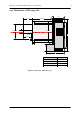
Figure 4.2: Side view of PD-109-57-RS V2 ...................................................................................................................... 9
Figure 4.3: Front view of PD-109-57-RS V2 .................................................................................................................. 10
Figure 4.4: Rear view of PD-109-57-RS V2 .................................................................................................................... 10
Figure 4.5: The TMCM-109 module and its connectors ............................................................................................ 11
Figure 5.1: GPI1, GPI2, and disable inputs .................................................................................................................. 15
Figure 5.2: Example for GPI1, GPI2, and disable inputs .......................................................................................... 15
Figure 6.1: Main parts of the PDx-109-57-RS V2 ......................................................................................................... 16
Figure 6.2: Pins for resetting the module ................................................................................................................... 21
List of Tables
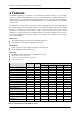
Table 2.1: Specifications of the PANdrive motors ....................................................................................................... 5
Table 3.1: Order codes ......................................................................................................................................................... 7
Table 4.1: Connector 1 ....................................................................................................................................................... 12
Table 4.2: Connector 2 ....................................................................................................................................................... 12
Table 5.1: Operational ratings ......................................................................................................................................... 14
Table 6.1: Motor current examples ................................................................................................................................ 18
Table 6.2: Microstep resolution setting ........................................................................................................................ 19
Table 6.3: Optimum motor settings ................................................................ Fehler! Textmarke nicht definiert.
Table 6.4: State indication LEDs...................................................................................................................................... 20
Table 8.1: TMC428 velocity parameters ......................................................................................................................... 23
Table 10.1: Document revision ........................................................................................................................................ 26
Table 10.2: Firmware revision ......................................................................................................................................... 26