PDx-109-57 V2 Hardware Manual Version: 1.13 2010-SEP-25 Trinamic Motion Control GmbH & Co KG Sternstraße 67 D - 20 357 Hamburg, Germany http://www.trinamic.
PDx-109-57 V2 Hardware Manual (V1.13 / 2010-SEP-25) Contents 1 2 3 4 5 6 7 8 9 10 11 Life support policy ....................................................................................................................................................... 4 Features........................................................................................................................................................................... 5 Order codes.......................................................
PDx-109-57 V2 Hardware Manual (V1.13 / 2010-SEP-25) List of Figures Figure Figure Figure Figure Figure Figure Figure Figure Figure 4.1: 4.2: 4.3: 4.4: 4.5: 5.1: 5.2: 6.1: 6.2: Dimensions of base PCB ............................................................................................................................... 8 Side view of PD-109-57-RS V2 ......................................................................................................................
PDx-109-57 V2 Hardware Manual (V1.13 / 2010-SEP-25) 1 Life support policy TRINAMIC Motion Control GmbH & Co. KG does not authorize or warrant any of its products for use in life support systems, without the specific written consent of TRINAMIC Motion Control GmbH & Co. KG. Life support systems are equipment intended to support or sustain life, and whose failure to perform, when properly used in accordance with instructions provided, can be reasonably expected to result in personal injury or death.
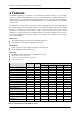
PDx-109-57 V2 Hardware Manual (V1.13 / 2010-SEP-25) 5 2 Features The PANdrive PDx-109-57 V2 features a full mechatronic solution including a 57mm flange motor. It is based on the TMCM-109-57 electronics and offers RS232 and RS485 interfaces. The power supply, the interface and the multipurpose I/Os can be connected via two pluggable screw terminal connectors. With the stallGuard™ feature it is possible to detect motor overload or motor stall.
PDx-109-57 V2 Hardware Manual (V1.13 / 2010-SEP-25) Interface RS232, RS485 (please request for CAN version) 2 inputs for reference and stop switches 3 general purpose inputs and 1 general purpose output Features up to 16 times microstepping memory for 2048 TMCL commands automatic ramp generation in hardware on the fly alteration of motion parameters (e.g.
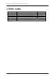
PDx-109-57 V2 Hardware Manual (V1.13 / 2010-SEP-25) 7 3 Order codes Order code PD1-109-57-option PD2-109-57-option PD3-109-57-option PD4-109-57-option Option RS Description PANdrive 0.55Nm PANdrive 1.01Nm PANdrive 1.26Nm PANdrive 1.89Nm Host interface RS232 and RS485 with with with with motor motor motor motor QSH5718-41-28-055 QSH5718-51-28-101 QSH5718-56-28-126 QSH5718-76-28-189 Table 3.1: Order codes Copyright © 2010, TRINAMIC Motion Control GmbH & Co. KG Dimensions 74.6 x 57.2 x 86 84.6.6 x 57.
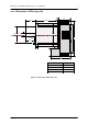
PDx-109-57 V2 Hardware Manual (V1.13 / 2010-SEP-25) 8 4 Electrical and mechanical interfacing 4.1 Dimensions 4.1.1 Dimensions of PCB Height: 22mm (additional: minimum 3mm distance to the motor; 4-5mm are recommended) The PCB has four M3 mounting holes for the QMOT motor configuration. 5.0 mm 4.1 mm TMCM-109-57 Mouning holes 28.0 mm 30.0 mm 86.0 mm Figure 4.1: Dimensions of base PCB Copyright © 2010, TRINAMIC Motion Control GmbH & Co. KG 49.0 mm 50.0 mm 57.2 mm 3.6 mm 23.
PDx-109-57 V2 Hardware Manual (V1.13 / 2010-SEP-25) 9 4.1.2 Dimensions of PDx-109-57 V2 2 24±1 30 Length 38.1±0.03 6,35-0.012 56.4±1 67 86 R 0.5 20±0.5 1.6 5 20 46 Motor QSH5718-41-28-055 QSH5718-51-28-101 QSH5718-56-28-126 QSH5718-76-28-189 Figure 4.2: Side view of PDx-109-57 V2 Copyright © 2010, TRINAMIC Motion Control GmbH & Co.
PDx-109-57 V2 Hardware Manual (V1.13 / 2010-SEP-25) 10 56.4±1 47.14±0.2 8.6 6.35-0.013 47.14±0.2 86.0 56.4±1 38.1±0.025 21.0 57.2 Figure 4.3: Front view of PDx-109-57 V2 32 86.0 32 67 Ø 2.5 57.2 Figure 4.4: Rear view of PDx-109-57 V2 Copyright © 2010, TRINAMIC Motion Control GmbH & Co. KG 4-ø4.
PDx-109-57 V2 Hardware Manual (V1.13 / 2010-SEP-25) 11 4.2 Connectors The TMCM-109 consists of two PCBs: the CPU board and the base board. All the connectors can be found on the base board. They are shown in Figure 4.5. The connectors onboard of the module are a 10 and a 12 pin female connector from RIACON, Type 183, RM 3.5mm. Fitting male connectors with screw terminals are RIACON Type 169, RM 3.5mm. Please refer to www.riaconnect.com for more detailed information.
PDx-109-57 V2 Hardware Manual (V1.13 / 2010-SEP-25) 4.2.1 Connector 1: Power supply, RS485, and GPI1/2 Use this connector to connect the module to the power supply. The connector also provides pins for the RS485 and the general purpose input 1 and 2 signals. To use the RS485 interface, it has to be enabled via the interface selection input (please see connector 2 pinning). The polarity of the shutdown input can be configured using TMCL™.
PDx-109-57 V2 Hardware Manual (V1.13 / 2010-SEP-25) 4.2.3 Connectors 3 and 4: Motor Normally, the TMCM-109 module comes mounted on a suitable stepper motor. Should you have a module without a motor you can connect a two phase bipolar stepper motor yourself. To connect the motor there are two screw terminals adjacent to a cable feed through hole on the board. Connect one coil of the motor to one of the connectors and the other coil to the other connector.
PDx-109-57 V2 Hardware Manual (V1.13 / 2010-SEP-25) 14 5 Operational ratings The operational ratings show the intended range for the values and should be used as design values. In no case shall the maximum values be exceeded. Symbol Parameter Min Typ. Max 1) 1) Unit VS ICOIL Power supply voltage for operation Motor coil current for sine wave peak (chopper regulated, adjustable via software) 18 0 24… 48 2.1 … 5.0 55 5.
PDx-109-57 V2 Hardware Manual (V1.13 / 2010-SEP-25) 15 5.1 GPI1, GPI2, and disable inputs The GPI1 input, the GPI2 input, and the disable input are optically isolated inputs. Their functional voltages VOPTON and VOPTOFF are directly depending on the input voltages (VGPI1, VGPI2 and VDISABLE). For offstate the input voltage has to be less than 1.5V (VOPTOFF) and for on-state it has to exceed 4.0V (VOPTON). + 5V V GPI1 5.. 24V V GPI2 5.. 24V V DISABLE 5..
PDx-109-57 V2 Hardware Manual (V1.13 / 2010-SEP-25) 16 6 Functional description In figure 6.1 the main parts of the PDx-109-57-RS V2 are shown. The module mainly consists of the µC, a TMC428 motion controller, a TMC249 stepper motor driver, the TMCL™ program memory (EEPROM) and the host interfaces RS232 and RS485.
PDx-109-57 V2 Hardware Manual (V1.13 / 2010-SEP-25) 6.1.4 TMC249 motor driver The stepper motor driver used on the TMCM-109 module is the TMC249 chip. This driver is very dependable, because it provides a variety of protection and diagnostic features, which even can be read out by the user software. It’s 16 times microstepping gives a quiet and precise motor operation. A maximum coil current of 5.0A is supported by this driver IC together with the high performance MOSFETs the module is equipped with. 6.
PDx-109-57 V2 Hardware Manual (V1.13 / 2010-SEP-25) 6.4 Communication interfaces RS232 and RS485 The communication between the host and the module takes place via its host interface. This can be either RS232 or RS485. The module is equipped with both interfaces, but only one interface can be used at a time. All interfaces integrated on the module are ready-to-use, so there are no external drivers or level shifters necessary.
PDx-109-57 V2 Hardware Manual (V1.13 / 2010-SEP-25) 6.6 Microstep resolution The microstep resolution can be set using TMCL™ software. The default setting is 64 microsteps which is the highest resolution. To set the microstep resolution with a TMCL™ command use instruction 5: SAP, type 140: microstep resolution You can find the appropriate value in Table 6.2: Value 0 1 2 3 4 5 6 Microsteps Do not use: for fullstep please see fullstep threshold Halfstep (not recommended) 4 8 16 32 64 Table 6.
PDx-109-57 V2 Hardware Manual (V1.13 / 2010-SEP-25) mounted to cope with higher environment temperatures, when problems are perceived. The 5V power supply output can be used to operate a small fan. 6.10 State indication LEDs The TMCM-109 module is equipped with four LEDs that show the actual state of the module: LED POWER CPU_OK ERROR OUT_0 Function Shows that the module is powered Flashes during normal operation.
PDx-109-57 V2 Hardware Manual (V1.13 / 2010-SEP-25) 6.12 Resetting the module The reset to factory default values can be done using the TMCL-IDE. Select Setup, Configure module, the Other tab and then Restore Factory Default. If there are communication problems, the reset procedure of the PDx-109-57 is as follows: 1. 2. 3. 4. 5. 6. 7. Turn OFF the power. Link pins 1 and 3 of the programming connector (as shown in the picture below) by hardwire.
PDx-109-57 V2 Hardware Manual (V1.13 / 2010-SEP-25) 7 Putting the PDx-109-57 into operation On the basis of a small example it is shown step by step how the PDx-109-57 is set into operation. Users who are already familiar with TMCL™ and other TRINAMIC modules may skip this chapter. Example: The following application is to be implemented on the TMCM-109 module using the TMCL-IDE Software development environment.
PDx-109-57 V2 Hardware Manual (V1.13 / 2010-SEP-25) 8 TMCM-109 operational description 8.1 Calculation: Velocity and acceleration vs. microstep- and fullstep frequency The values of the parameters sent to the TMC428 do not have typical motor values, like rotations per second as velocity. But these values can be calculated from the TMC428 parameters, as shown in the table below. It is also possible to use the calculator of the TMCL-IDE.
PDx-109-57 V2 Hardware Manual (V1.13 / 2010-SEP-25) Example: CLK velocity a_max pulse_div ramp_div usrs 16MHz on the TMCM-109 module 1000 1000 1 1 6 16 MHz 1000 122070.3125 Hz 21 2048 32 msf fsf [ Hz ] a 122070.3125 1907.35Hz 26 (16Mhz) 2 1000 MHz 119.208 1 1 29 s 2 119.208 af 2 6 MHz s 1,863 MHz s If the stepper motor has e.g. 72 fullsteps per rotation, the number of rotations of the motor is: RPS RPM fsf 1907.35 26.49 fullsteps per rotation 72 fsf 60 1907.35 60 1589.
PDx-109-57 V2 Hardware Manual (V1.13 / 2010-SEP-25) 9 Software TMCL™, the Trinamic Motion Control Language is used to send commands from the host to the TMCM109 module and to write programs that can be stored in the EEPROM of the module so that the module can execute the TMCL™ commands in a stand-alone mode. TMCL™ is described in the PDx-109-57 V2 Firmware Manual.
PDx-109-57 V2 Hardware Manual (V1.13 / 2010-SEP-25) 26 10 Revision history 10.1 Document revision Version 1.00 1.01 1.03 1.04 1.06 1.07 1.08 1.09 Comment Initial Release 2005-JUN-29 2005-DEC-09 2005-DEC-15 2006-MAR-12 2006-JUL-13 2006-OCT-18 2007-JUN-06 Author OK BD BD, HC BD BD BD HC HC 1.10 1.11 1.12 2007-OCT-17 2008-DEC-08 2010-JAN-15 HC OK SD 1.
PDx-109-57 V2 Hardware Manual (V1.13 / 2010-SEP-25) 11 References [PDx-109] [TMCL-IDE] [QSH5718] PDx-109-57 Vs TMCL™ Firmware Manual TMCL-IDE User Manual QSH5718 Manual Please see http://www.trinamic.com. Copyright © 2010, TRINAMIC Motion Control GmbH & Co.