
User manual


TMCM-1140 TMCL Firmware V1.19 Manual (Rev. 1.01 / 2012-JUL-27) 7
www.trinamic.com
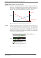
1. Connect power supply and choose your interface
a) Connect CAN or RS485 and power supply
CAN interface will be de-activated in case USB is connected due to internal sharing of hardware
resources.
Pin
Label
Description
1
GND
System and signal ground
2
VDD
VDD (+9V…+28V)
3
RS485+
RS485 interface, diff. signal (non-inverting)
4
RS485-
RS485 interface, diff. signal (inverting)
5
CAN_H
CAN interface, diff. signal (non-inverting)
6
CAN_L
CAN interface, diff. signal (inverting)
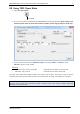
b) Connect USB interface (as alternative to CAN and RS485; use a normal USB cable)
Download and install the file TMCM-1140.inf (www.trinamic.com).
Pin
Label
Description
1
VBUS
+5V power
2
D-
Data –
3
D+
Data +
4
ID
ground
5
GND
ground
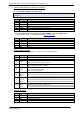
2. Connect In/Out connector
If you like to work with the GPIOs or switches, use the In/Out connector.
Pin
Label
Description
1
GND
System and signal ground
2
VDD
VDD, connected to VDD pin of the power and communication connector
3
OUT_1
Open-drain output (max. 1A)
Integrated freewheeling diode to VDD
4
OUT_0
+5V supply output (max. 100mA)
Can be switched on/off in software
5
AIN_0
Dedicated analog input,
Input voltage range: 0..+10V
Resolution: 12bit (0..4095)
6
IN_0,
STOP_L,
ENC_A
General purpose digital input (+24V compatible)
Alternate function 1: left stop switch input
Alternate function 2: external incremental encoder channel A input
7
IN_1,
STOP_R,
ENC_B
General purpose digital input (+24V compatible)
Alternate function 1: right stop switch input
Alternate function 2: external incremental encoder channel B input
8
IN_2,
HOME,
ENC_N
General purpose digital input (+24V compatible)
Alternate function 1: home switch input
Alternate function 2: external incremental encoder index / zero channel input
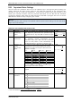
3. Connect the motor
Pin
Label
Description
1
OB2
Pin 2 of motor coil B
2
OB1
Pin 1 of motor coil B
3
OA2
Pin 2 of motor coil A
4
OA1
Pin 1 of motor coil A