
User manual

TMCM-1021 TMCL Firmware V1.19 Manual (Rev. 1.04 / 2012-JUL-30) 60
www.trinamic.com
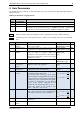
4 Axis Parameters
The following sections describe all axis parameters that can be used with the SAP, GAP, AAP, STAP and
RSAP commands.
Meaning of the letters in column Access:
Access
type
Related
command(s)
Description
R
GAP
Parameter readable
W
SAP, AAP
Parameter writable
E
STAP, RSAP
Parameter automatically restored from EEPROM after reset or power-on. These
parameters can be stored permanently in EEPROM using STAP command and
also explicitly restored (copied back from EEPROM into RAM) using RSAP
Basic parameters should be adjusted to motor / application for proper module operation.
Parameters for the more experienced user – please do not change unless you are absolutely
sure.
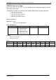
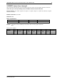
Number
Axis Parameter
Description
Range [Unit]
Acc.
0
Target (next)
position
The desired position in position mode (see
ramp mode, no. 128).
−2.147.483.648…
+2.147.483.647 [µsteps]
RW
1
Actual position
The current position of the motor. Should only
be overwritten for reference point setting.
−2.147.483.648…
+2.147.483.647 [µsteps]
RW
2
Target (next)
speed
The desired speed in velocity mode (see ramp
mode, no. 128). In position mode, this
parameter is set automatically: to the maximum
speed during acceleration, and to zero during
deceleration and rest.
-268.435.455…
+268.435.454
[pps]
RW
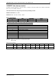
3
Actual speed
The current rotation speed.
-268.435.455…
+268.435.454 [pps]
RW
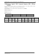
4
Maximum
positioning
speed
Maximum feasible positioning speed. Has to be
adapted to motor and application
0… +268.435.454
[pps]
RWE
5
Maximum
acceleration
Limit for acceleration and deceleration. Has to
be adapted to motor and application.
1… +33554431
[pps/s]
RWE
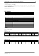
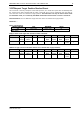
6
Max. motor run
current
Attention: setting motor current too high might
permanently damage the motor!
The maximum value is 255. This value means
100% of maximum programmable current of the
module. Current can be adjusted / scaled down
by specifying a lower value between 0 and 255.
This value is transformed into 32 different
internal current settings supported by the
hardware (0… 255 divided by eight; e.g. 0… 7 ->
1/32 of max. current, 8… 15 -> 2/32 of max.
Current … 247…255 -> max. current).
0… 255
RWE
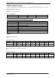
7
Standby current
Current limit after the motor has stopped plus
power down delay time (see parameter 214).
Same range and meaning as for parameter 6
0… 255
RWE
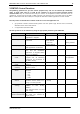
8
Position reached
1 when target position = actual position
0 otherwise
0/1
R
9
Home switch
status
The logical state of the home switch.
0/1
R