
User manual


TMCM-1021 V1.2 Hardware Manual (Ref. 1.00 / 2012-MAR-09) 9
www.trinamic.com
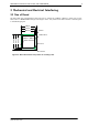
3.3 Power Supply
For proper operation care has to be taken with regard to power supply concept and design. Due to space
restrictions the TMCM-1021 includes just about 20µF/35V of supply filter capacitors. These are ceramic
capacitors which have been selected for high reliability and long life time. The module includes a 28V
suppressor diode for over-voltage protection. There is no reverse polarity protection. The module will short
any reversed supply voltage due to internal diodes of the driver transistors.
It is absolutely necessary that the power supply voltage is kept below the upper limit of 28V under all
circumstances (please see also chapter 6, operating values). Otherwise the driver electronics might be
seriously damaged! Especially, when the selected operating voltage is near the upper limit a regulated
power supply is highly recommended.
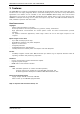
It is recommended to connect an electrolytic capacitor of significant size (e.g. 470µF/35V) to the power
supply lines next to the TMCM-1021!
Rule of thumb for size of electrolytic capacitor:
In addition to power stabilization (buffer) and filtering this added capacitor will also reduce any voltage
spikes which might otherwise occur from a combination of high inductance power supply wires and the
ceramic capacitors. In addition it will limit slew-rate of power supply voltage at the module. The low ESR of
ceramic-only filter capacitors may cause stability problems with some switching power supplies.
3.4 Communication
3.4.1 RS485
For remote control and communication with a host system the TMCM-1021 provides a two wire RS485 bus
interface. For proper operation the following items should be taken into account when setting up an RS485
network:
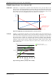
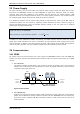
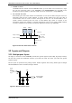
1. BUS STRUCTURE:
The network topology should follow a bus structure as closely as possible. That is, the connection
between each node and the bus itself should be as short as possible. Basically, it should be short
compared to the length of the bus.
c:>
node
1
node
n
- 1
node
n
Host
Slave Slave Slave
RS485
termination
resistor
(120 Ohm)
termination
resistor
(120 Ohm)
}
keep distance as
short as possible
Figure 3.5: Bus structure
2. BUS TERMINATION:
Especially for longer busses and/or multiple nodes connected to the bus and/or high communication
speeds, the bus should be properly terminated at both ends. The TMCM-1021 does not integrate any
termination resistor. Therefore, 120 Ohm termination resistors at both ends of the bus have to be
added externally.