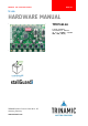
MODULES FOR STEPPER MOTORS MODULES V 1.10 HARDWARE MANUAL + + TMCM-6110 6-axes stepper controller / driver up to 1.1A RMS / 24V DC USB, CAN, RS485 + TRINAMIC Motion Control GmbH & Co. KG Hamburg, Germany www.trinamic.
TMCM-6110 Hardware Manual (V1.10 / 2012-JAN-25) Table of contents 1 2 3 4 Life support policy ....................................................................................................................................................... 3 Features ........................................................................................................................................................................... 4 Order codes ...................................................................
TMCM-6110 Hardware Manual (V1.10 / 2012-JAN-25) 1 Life support policy TRINAMIC Motion Control GmbH & Co. KG does not authorize or warrant any of its products for use in life support systems, without the specific written consent of TRINAMIC Motion Control GmbH & Co. KG. Life support systems are equipment intended to support or sustain life, and whose failure to perform, when properly used in accordance with instructions provided, can be reasonably expected to result in personal injury or death.
TMCM-6110 Hardware Manual (V1.10 / 2012-JAN-25) 4 2 Features The TMCM-6110 is a compact 6-axes stepper motor controller / driver standalone board. It supports up to 6 bipolar stepper motors with up to 1.1A RMS coil current. There are separate motor and reference / end-switch connectors for each motor. In addition, the module offers 8 general purpose inputs and 8 general purpose outputs.
TMCM-6110 Hardware Manual (V1.10 / 2012-JAN-25) 5 3 Order codes The standalone module TMCM-6110 is available as: Order code TMCM-6110-option Description 6-axes bipolar stepper motor controller / driver module Size of unit 130mm x 100mm x 30mm Table 3.1: TMCM-6110 order codes The following options are available: Firmware option -TMCL Description Module pre-programmed with TMCL firmware Order code example: TMCM-6110-TMCL Table 3.
TMCM-6110 Hardware Manual (V1.10 / 2012-JAN-25) 6 4 Mechanical and electrical interfacing 4.1 Size of board The board with the controller / driver electronics has an overall size of 130mm x 100mm and offers four mounting holes for M3 screws (3.2mm diameter): 130 125 5 5 4x M3 screws for mounting 100 95 5 Figure 4.1: Board dimensions and position of mounting holes (all values in mm). Maximum board height (without mating connectors and cable looms) is about 30mm (approx.
TMCM-6110 Hardware Manual (V1.10 / 2012-JAN-25) 7 4.2 Board mounting considerations The TMCM-6110 offers four metal plated mounting holes. All four mounting holes are connected to system and signal ground (same as power supply ground). In order to minimize distortion of signals and radiation of HF signals (improve EMC compatibility) especially in sensitive / noisy environments it is important to ensure a solid ground connection within the system.
TMCM-6110 Hardware Manual (V1.10 / 2012-JAN-25) 8 4.3 Connectors The TMCM-6110 has 18 connectors altogether. There are 6 separate connectors for each motor and corresponding reference switches (Figure 4.4), two I/O connectors, one power connector and 3 connectors for communication incl. Mini-USB, RS485 and CAN.
TMCM-6110 Hardware Manual (V1.10 / 2012-JAN-25) 9 4.3.1 Power connector The module offers a single power connector with the option to have separate supply for driver electronics and digital controller part. A single supply voltage is sufficient, all further voltages required e.g. for the digital components are generated on-board.
TMCM-6110 Hardware Manual (V1.10 / 2012-JAN-25) 10 4.3.3 I/O connector 1 The module offers two I/O connectors. The number and type of inputs, outputs and supply is the same for both connectors. Therefore, if only half of the inputs / outputs etc. is required it will be sufficient to use just one of the two connectors and reduce / simplify cabling. Connector type is JST PH series 8pin with 2mm pitch.
TMCM-6110 Hardware Manual (V1.10 / 2012-JAN-25) 11 4.3.6 CAN connector A CAN 2.0B interface is available via a standard 9-pin male D-SUB connector. Only three pins of this connector are used. Pin assignment of these three pins is according to CiA Draft Recommendation Part 1: Cabling and connector pin assignment. Please note: CAN interface will be de-activated in case USB is connected due to internal sharing of hardware resources.
TMCM-6110 Hardware Manual (V1.10 / 2012-JAN-25) 12 4.4 Power supply For proper operation care has to be taken with regard to power supply concept and design. The board offers 2000uF / 35V electrolytic buffer capacitors and additionally about 120uF / 35V ceramic capacitors for supply voltage filtering. It is important that the power supply voltage (VDRIVER and VDIGITAL) is kept below the upper limit of 28V DC.
TMCM-6110 Hardware Manual (V1.10 / 2012-JAN-25) 13 2. BUS TERMINATION: Especially for longer busses and/or multiple nodes connected to the bus and/or high communication speeds, the bus should be properly terminated at both ends. The TMCM-6110 does not integrate any termination resistor. Therefore, 120 Ohm termination resistors at both ends of the bus have to be added externally. 3. NUMBER OF NODES: The RS-485 electrical interface standard (EIA-485) allows up to 32 nodes to be connected to a single bus.
TMCM-6110 Hardware Manual (V1.10 / 2012-JAN-25) 14 6. BUS TERMINATION: Especially for longer busses and/or multiple nodes connected to the bus and/or high communication speeds, the bus should be properly terminated at both ends. The TMCM-6110 does not integrate any termination resistor. Therefore, 120 Ohm termination resistors at both ends of the bus have to be added externally. 7.
TMCM-6110 Hardware Manual (V1.10 / 2012-JAN-25) 15 4.6.2 General purpose Inputs The TMCM-6110 offers two I/O connectors with 8 inputs altogether including two dedicated analog inputs. All inputs offer the same basic input protection circuit. The dedicated analog inputs have different input voltage dividers in order to support a full scale input voltage range of 0…+10V. The other digital inputs have been designed in order to be able to accept +5V and +24V signal levels.
TMCM-6110 Hardware Manual (V1.10 / 2012-JAN-25) 16 4.6.3 General purpose outputs The TMCM-6110 offers two I/O connectors with 8 outputs altogether. All outputs are open-drain outputs. For all outputs a freewheeling diode (to VDIGTAL) is already integrated. Nevertheless, two output offer more powerful MOSFET driver transistors supporting currents up to 1A. All other have been designed for currents up to 100mA.
TMCM-6110 Hardware Manual (V1.10 / 2012-JAN-25) 17 5 On-board LEDs The board offers two LEDs in order to indicate board status. The function of both LEDs is dependent on firmware version. With standard TMCL firmware the green LED should be slowly flashing during operation and the red LED should be off. Please see separate TMCM-6110 TMCL™ firmware manual for additional information. When there is no valid firmware programmed into the board or during firmware update the red and green LEDs are permanently on.
TMCM-6110 Hardware Manual (V1.10 / 2012-JAN-25) 18 6 Reset to factory defaults Since TMCL firmware version V1.13 it is possible to reset the TMCM-6110 module to factory default settings without establishing a communication link. This might be helpful in case communication parameters of the preferred interface have been set to unknown values or got accidentally lost. For this procedure two pads on the bottom side of the board have to be shortened (see figure 4.12). Please perform the following steps: 1. 2.
TMCM-6110 Hardware Manual (V1.10 / 2012-JAN-25) 19 7 Functional description The TMCM-6110 is a highly integrated 6-axes controller / driver module. The TMCM-6110 can be controlled via CAN, RS485 or USB serial interfaces. The TMCM-6110 comes with the PC based software development environment TMCL-IDE for the Trinamic Motion Control Language (TMCL™). Using predefined TMCL™ high level commands like move to position a rapid and fast development of motion control applications is guaranteed.
TMCM-6110 Hardware Manual (V1.10 / 2012-JAN-25) 20 8 Operational ratings The operational ratings show the intended or the characteristic ranges and should be used as design values. In no case shall the maximum values be exceeded. Symbol Parameter Min Typ Max Unit VDRIVER Power supply voltage for driver 9 12 ...
TMCM-6110 Hardware Manual (V1.10 / 2012-JAN-25) Symbol Parameter NRS485 Number of nodes connected to single RS485 network 21 Min Typ Max 256 Table 8.4: Operational ratings of the RS485 interface 9 Revision History 9.1 Document revision Version 0.90 1.00 1.01 Date 2011-AUG-17 2011-SEP-13 2011-NOV-11 Author GE SD SD 1.10 2012-JAN-25 GE Description Preliminary version First complete version, minor changes Minor changes, TENV in chapter 8 added.