
User manual

TMCM-6110 TMCL Firmware V1.19 Manual (Rev. 1.03 / 2012-JUL-31) 7
www.trinamic.com
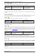
4.1.1.1 Power Supply
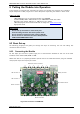
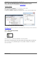
Connect the power supply with the power supply connector (see Figure 4.1).
Label
Connector type
Mating connector type
Power Connector
JST B3P-VH
(JST VH series, 3pins, 3.96mm pitch)
Connector housing: JST VHR-3N
Contacts: JST SVH-21T-P1.1
Wire: 0.83mm
2
, AWG 18
Do not exceed the maximum power supply of +28V DC!
The device is protected against wrong polarity by a diode that shorts the power supply when the polarity
is wrong.
4.1.1.2 Communication
Choose your communication interface out of three serial interfaces: RS485, USB and CAN. If you need more
information about the interfaces (e.g. pin assignments), refer to the Hardware Manual, please.
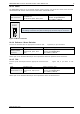
4.1.1.2.1 RS485
Connect the RS485 interface with the appropriate connector (see Figure 4.1).
Label
Connector type
Mating connector type
RS485 Connector
Tyco electronics 3-1634218-2 D-SUB
socket with 4-40 female screw locks
Any standard D-SUB female 9-pin
RS485 as field bus interface normally requires an adapter. From TRINAMIC the USB-2-485 converter between
USB and RS485 is available.
4.1.1.2.2 USB
Connect the USB interface with the appropriate connector (see Figure 4.1). To make use of the USB
interface, a device driver has to be installed first. When the TMCM-6110 module is connected to the USB
interface of a PC for the first time, you will be prompted for a driver by the operating system. The tmcm-
6110.inf file is available on www.trinamic.com. After downloading and installing the driver the module is
ready for use.
Label
Connector type
Mating connector type
Mini-USB connector
Molex 500075-1517 Mini USB Type B
vertical receptacle
Any standard mini-USB plug
CAN interface will be deactivated as soon as USB is connected (V
BUS
voltage available)
On-board digital core logic (mainly processor and EEPROM) will be powered via USB in case no other
supply is connected. This can be used to set parameters / download TMCL programs or perform firmware
updates with the module connected via USB only or inside the machine while the machine is powered off.
4.1.1.2.3 CAN
Connect the CAN interface with the appropriate connector (see Figure 4.1). The dip switch can be used for
setting the address of the module. If all switches are off the address set by global parameter 71 (CAN ID)
is valid.
Label
Connector type
Mating connector type
CAN connector
Male D-SUB 9-pin
Any standard D-SUB female 9-pin
TRINAMIC offers the CANnes card, which is a CAN-bus PCI-card and provides a simple and easy use of the
CAN interface.
CAN interface will be de-activated in case USB is connected due to internal sharing of hardware resources.