
User manual

TMCM-6110 TMCL Firmware V1.19 Manual (Rev. 1.03 / 2012-JUL-31) 39
www.trinamic.com
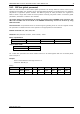
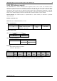
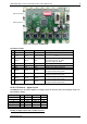
1
10
1
10
I/O connector 0
I/O connector 1
Figure 5.2: connectors of TMCM-6110
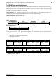
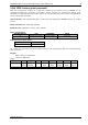
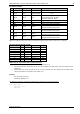
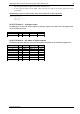
I/O CONNECTOR 0 AND 1
Pin
Connector 0
Connector 1
Direction
Description
1
GND
GND
Power (GND)
GND
2
V
DIGITAL
V
DIGITAL
Power
(supply output)
Connected to V
DIGITAL
of Power connector
3
AIN_0
AIN_4
Input
Dedicated analog input,
input voltage range: 0… +10V,
resolution: 12bit (0… 4095)
4
IN_1
IN_5
Input
Digital input (+24V compatible)
5
IN_2
IN_6
Input
Digital input (+24V compatible)
6
IN_3
IN_7
Input
Digital input (+24V compatible)
7
OUT_0
OUT_4
Output
Open-drain output (max. 100mA)
Integrated freewheeling diode
8
OUT_1
OUT_5
Output
Open-drain output (max. 100mA)
Integrated freewheeling diode
9
OUT_2
OUT_6
Output
Open-drain output (max. 100mA)
Integrated freewheeling diode
10
OUT_3
OUT_7
Output
Open-drain output (max. 1A)
Integrated freewheeling diode
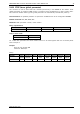
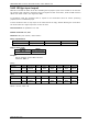
5.6.15.1 I/O bank 0 – digital inputs:
The ADIN lines can be read as digital or analogue inputs at the same time. The analogue values can
be accessed in bank 1.
Reading all digital inputs with one GIO command:
I/O Connector
Pin
I/O port
Command
Range
0
4
IN_1
GIO 1, 0
0/1
0
5
IN_2
GIO 2, 0
0/1
0
6
IN_3
GIO 3, 0
0/1
1
4
IN_5
GIO 5, 0
0/1
1
5
IN_6
GIO 6, 0
0/1
1
6
IN_7
GIO 7, 0
0/1