
User manual

TMCM-6110 TMCL Firmware V1.19 Manual (Rev. 1.03 / 2012-JUL-31) 37
www.trinamic.com
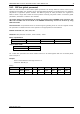
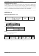
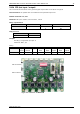
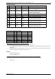
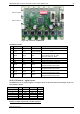
I/O CONNECTOR 0 AND 1
Pin
Connector 0
Connector 1
Direction
Description
1
GND
GND
Power (GND)
GND
2
V
DIGITAL
V
DIGITAL
Power
(supply output)
Connected to V
DIGITAL
of power connector
3
AIN_0
AIN_4
Input
Dedicated analog input,
input voltage range: 0… +10V,
resolution: 12bit (0… 4095)
4
IN_1
IN_5
Input
Digital input (+24V compatible)
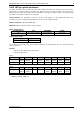
5
IN_2
IN_6
Input
Digital input (+24V compatible)
6
IN_3
IN_7
Input
Digital input (+24V compatible)
7
OUT_0
OUT_4
Output
Open-drain output (max. 100mA)
Integrated freewheeling diode
8
OUT_1
OUT_5
Output
Open-drain output (max. 100mA)
Integrated freewheeling diode
9
OUT_2
OUT_6
Output
Open-drain output (max. 100mA)
Integrated freewheeling diode
10
OUT_3
OUT_7
Output
Open-drain output (max. 1A)
Integrated freewheeling diode
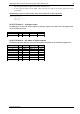
Bank 2 is used for setting the status of the general digital output either to low (0) or to high (1).
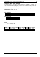
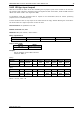
I/O PORTS USED FOR SIO AND COMMAND
I/O Connector
Pin
I/O port
Command
Range
0
7
OUT_0
SIO 0, 2, <n>
1/0
0
8
OUT_1
SIO 1, 2, <n>
1/0
0
9
OUT_2
SIO 2, 2, <n>
1/0
0
10
OUT_3
SIO 3, 2, <n>
1/0
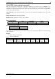
1
7
OUT_4
SIO 4, 2, <n>
1/0
1
8
OUT_5
SIO 5, 2, <n>
1/0
1
9
OUT_6
SIO 6, 2, <n>
1/0
1
10
OUT_7
SIO 7, 2, <n>
1/0
Addressing all output lines with one SIO command:
Set the type parameter to 255 and the bank parameter to 2.
The value parameter must then be set to a value between 0… 255, where every bit represents one
output line.
Furthermore, the value can also be set to -1. In this special case, the contents of the lower 8 bits
of the accumulator are copied to the output pins.
Example:
Set all output pins high.
Mnemonic: SIO 255, 2, 3
The following program will show the states of the input lines on the output lines:
Loop: GIO 255, 0
SIO 255, 2,-1
JA Loop