MODULE FOR STEPPER MOTORS MODULE Firmware Version V1.19 TMCL™ FIRMWARE MANUAL + + TMCM-6110 6 axes stepper controller / driver up to 1.1A RMS / 24V DC USB, CAN, RS485 [or RS232] + TRINAMIC Motion Control GmbH & Co. KG Hamburg, Germany www.trinamic.
TMCM-6110 TMCL Firmware V1.19 Manual (Rev. 1.03 / 2012-JUL-31) Table of Contents 2 3 4 Features........................................................................................................................................................................... 4 Overview ......................................................................................................................................................................... 5 Putting the Module into Operation ..........................
TMCM-6110 TMCL Firmware V1.19 Manual (Rev. 1.03 / 2012-JUL-31) 5.6.35 RETI (return from interrupt) ..................................................................................................................... 60 5.6.36 Customer Specific TMCL Command Extension (UF0… UF7 - user function) ................................ 61 5.6.37 Request Target Position Reached Event ............................................................................................... 62 5.6.38 BIN (return to binary mode) ..
TMCM-6110 TMCL Firmware V1.19 Manual (Rev. 1.03 / 2012-JUL-31) 2 Features The TMCM-6110 is a compact 6-axes stepper motor controller/driver standalone board. It supports up to 6 bipolar stepper motors with up to 1.1A RMS coil current. There are separate motor and reference/end switch connectors for each motor. In addition, the module offers 8 general purpose inputs and 8 general purpose outputs.
TMCM-6110 TMCL Firmware V1.19 Manual (Rev. 1.03 / 2012-JUL-31) 3 Overview The software running on the microprocessor of the TMCM-6110 consists of two parts, a boot loader and the firmware itself. Whereas the boot loader is installed during production and testing at TRINAMIC and remains untouched throughout the whole lifetime, the firmware can be updated by the user. New versions can be downloaded free of charge from the TRINAMIC website (http://www.trinamic.com).
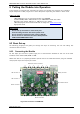
TMCM-6110 TMCL Firmware V1.19 Manual (Rev. 1.03 / 2012-JUL-31) 6 4 Putting the Module into Operation In this chapter you will find basic information for putting your module into operation. This includes a simple example for a TMCL program and a short description of operating the module in direct mode. THINGS YOU NEED - TMCM-6110 with up to six appropriate motors (e.g.
TMCM-6110 TMCL Firmware V1.19 Manual (Rev. 1.03 / 2012-JUL-31) 7 4.1.1.1 Power Supply Connect the power supply with the power supply connector (see Label Connector type Power Connector JST B3P-VH (JST VH series, 3pins, 3.96mm pitch) Figure 4.1). Mating connector type Connector housing: JST VHR-3N Contacts: JST SVH-21T-P1.1 Wire: 0.
TMCM-6110 TMCL Firmware V1.19 Manual (Rev. 1.03 / 2012-JUL-31) 8 4.1.1.3 Motor The TMCM-6110 controls up to six 2-phase stepper motors. Connect one coil of each motor to the terminals marked A0 and A1 and the other coil to the connectors marked B0 and B1. Label Connector type Motor connectors JST B4B-PH-K-S (JST PH series, 4pins, 2mm pitch) Mating connector type Connector housing: JST PHR-4 Contacts: JST SPH-002T-P0.5S Wire: 0.
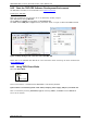
TMCM-6110 TMCL Firmware V1.19 Manual (Rev. 1.03 / 2012-JUL-31) 4.1.2 Start the TMCL-IDE Software Development Environment The TMCL-IDE is available on the TechLibCD and on www.trinamic.com. Installing the TMCL-IDE: Make sure the COM port you intend to use is not blocked by another program. Open TMCL-IDE by clicking TMCL.exe. Choose Setup and Options and thereafter the Connection tab. For RS485 choose COM port and type with the parameters shown in Figure 4.3 (baud rate 9600). Click OK. Figure 4.
TMCM-6110 TMCL Firmware V1.19 Manual (Rev. 1.03 / 2012-JUL-31) Examples: ROR rotate right, motor 0, value 500 MST motor stop, motor 0 10 -> Click Execute. The first motor is rotating now. -> Click Execute. The first motor stops now. Top right of the TMCL Direct Mode window is the button Copy to editor. Click here to copy the chosen command and create your own TMCL program. The command will be shown immediately on the editor. You will find a description of all TMCLTM commands in the following chapters.
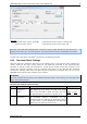
TMCM-6110 TMCL Firmware V1.19 Manual (Rev. 1.03 / 2012-JUL-31) Number 6 Axis Parameter absolute max. current (CS / Current Scale) Description The maximum value is 255. This value means 100% of the maximum current of the module. The current adjustment is within the range 0… 255 and can be adjusted in 32 steps.
TMCM-6110 TMCL Firmware V1.19 Manual (Rev. 1.03 / 2012-JUL-31) 1. 2. 3. 4. Click on Icon Assemble to convert the TMCL into machine code. Then download the program to the TMCM-6110 module via the icon Download. Press icon Run. The desired program will be executed. Click Stop button to stop the program. www.trinamic.
TMCM-6110 TMCL Firmware V1.19 Manual (Rev. 1.03 / 2012-JUL-31) 13 5 TMCL and TMCL-IDE The TMCM-6110 supports TMCL direct mode (binary commands or ASCII interface) and standalone TMCL program execution. You can store up to 2048 TMCL instructions on it. In direct mode and most cases the TMCL communication over RS485, USB or CAN follows a strict master/slave relationship. That is, a host computer (e.g. PC/PLC) acting as the interface bus master will send a command to the TMCM-6110.
TMCM-6110 TMCL Firmware V1.19 Manual (Rev. 1.03 / 2012-JUL-31) 14 Checksum calculation As mentioned above, the checksum is calculated by adding up all bytes (including the module address byte) using 8-bit addition.
TMCM-6110 TMCL Firmware V1.19 Manual (Rev. 1.03 / 2012-JUL-31) 15 5.3 Standalone Applications The module is equipped with an EEPROM for storing TMCL applications. You can use TMCL-IDE for developing standalone TMCL applications. You can load them down into the EEPROM and then it will run on the module. The TMCL-IDE contains an editor and the TMCL assembler where the commands can be entered using their mnemonic format. They will be assembled automatically into their binary representations.
TMCM-6110 TMCL Firmware V1.19 Manual (Rev. 1.03 / 2012-JUL-31) Command AGP VECT RETI ACO 5.4.2 Number 35 37 38 39 Parameter , ,
TMCM-6110 TMCL Firmware V1.19 Manual (Rev. 1.03 / 2012-JUL-31) Mnemonic SIO GIO Command number 14 15 17 Meaning Set output Get input 5.4.2.5 Calculation Commands These commands are intended to be used for calculations within TMCL applications. Although they could also be used in direct mode it does not make much sense to do so.
TMCM-6110 TMCL Firmware V1.19 Manual (Rev. 1.03 / 2012-JUL-31) 5.4.2.6.3 18 Interrupt Vectors: The following table shows all interrupt vectors that can be used. Interrupt number 0 1 2 3 15 21 27 28 39 40 255 5.4.2.6.4 Interrupt type Timer 0 Timer 1 Timer 2 Target position reached stallGuard™ Deviation Left stop switch Right stop switch Input change 0 Input change 1 Global interrupts Further Configuration of Interrupts Some interrupts need further configuration (e.g.
TMCM-6110 TMCL Firmware V1.19 Manual (Rev. 1.03 / 2012-JUL-31) #include Interrupts.inc VECT TI_TIMER0, Timer0Irq SGP TI_TIMER0, 3, 1000 EI TI_TIMER0 EI TI_GLOBAL Please also take a look at the other example programs. www.trinamic.
TMCM-6110 TMCL Firmware V1.19 Manual (Rev. 1.03 / 2012-JUL-31) 20 5.5 The ASCII Interface There is also an ASCII interface that can be used to communicate with the module and to send some commands as text strings. 5.5.1 The ASCII command line interface is entered by sending the binary command 139 (enter ASCII mode). Afterwards the commands are entered as in the TMCL-IDE. Please note that only those commands, which can be used in direct mode, also can be entered in ASCII mode.
TMCM-6110 TMCL Firmware V1.19 Manual (Rev. 1.03 / 2012-JUL-31) 21 Bit 4 and Bit 5 determine how the characters that are entered are echoed back. Normally, both bits are set to zero. In this case every character that is entered is echoed back when the module is addressed. Character can also be erased using the backspace character (press the backspace key in a terminal program).
TMCM-6110 TMCL Firmware V1.19 Manual (Rev. 1.03 / 2012-JUL-31) 22 5.6 Commands The module specific commands are explained in more detail on the following pages. They are listed according to their command number. 5.6.1 ROR (rotate right) The motor will be instructed to rotate with a specified velocity in right direction (increasing the position counter). Internal function: first, velocity mode is selected. Then, the velocity value is transferred to axis parameter #0 (target velocity).
TMCM-6110 TMCL Firmware V1.19 Manual (Rev. 1.03 / 2012-JUL-31) 5.6.2 23 ROL (rotate left) The motor will be instructed to rotate with a specified velocity (opposite direction compared to ROR, decreasing the position counter). Internal function: first, velocity mode is selected. Then, the velocity value is transferred to axis parameter #0 (target velocity). The module is based on the TMC429 stepper motor controller and the TMC260 power driver. This makes possible choosing a velocity between 0 and 2047.
TMCM-6110 TMCL Firmware V1.19 Manual (Rev. 1.03 / 2012-JUL-31) 5.6.3 24 MST (motor stop) The motor will be instructed to stop. Internal function: the axis parameter target velocity is set to zero. Related commands: ROL, ROR, SAP, GAP Mnemonic: MST Binary representation: INSTRUCTION NO.
TMCM-6110 TMCL Firmware V1.19 Manual (Rev. 1.03 / 2012-JUL-31) 5.6.4 25 MVP (move to position) The motor will be instructed to move to a specified relative or absolute position or a pre-programmed coordinate. It will use the acceleration/deceleration ramp and the positioning speed programmed into the unit. This command is non-blocking – that is, a reply will be sent immediately after command interpretation and initialization of the motion controller.
TMCM-6110 TMCL Firmware V1.19 Manual (Rev. 1.03 / 2012-JUL-31) 26 Example: Move motor 0 to previously stored coordinate #8 Mnemonic: MVP COORD, 0, 8 Binary: Byte Index Function Value (hex) 0 1 Target- Instruction address Number $01 $04 2 Type $02 3 Motor/ Bank $00 4 Operand Byte3 $00 5 Operand Byte2 $00 6 Operand Byte1 $00 7 Operand Byte0 $08 8 Checksum $11 When moving to a coordinate, the coordinate has to be set properly in advance with the help of the SCO, CCO or ACO command. www.trinamic.
TMCM-6110 TMCL Firmware V1.19 Manual (Rev. 1.03 / 2012-JUL-31) 5.6.5 27 SAP (set axis parameter) With this command most of the motion control parameters can be specified. The settings will be stored in SRAM and therefore are volatile. That is, information will be lost after power off. Please use command STAP (store axis parameter) in order to store any setting permanently. Internal function: the parameter format is converted ignoring leading zeros (or ones for negative values).
TMCM-6110 TMCL Firmware V1.19 Manual (Rev. 1.03 / 2012-JUL-31) 5.6.6 28 GAP (get axis parameter) Most parameters of the TMCM-6110 can be adjusted individually for the axis. With this parameter they can be read out. In standalone mode the requested value is also transferred to the accumulator register for further processing purposes (such as conditioned jumps). In direct mode the value read is only output in the value field of the reply (without affecting the accumulator).
TMCM-6110 TMCL Firmware V1.19 Manual (Rev. 1.03 / 2012-JUL-31) 5.6.7 29 STAP (store axis parameter) An axis parameter previously set with a Set Axis Parameter command (SAP) will be stored permanent. Most parameters are automatically restored after power up. Internal function: an axis parameter value stored in SRAM will be transferred to EEPROM and loaded from EEPORM after next power up.
TMCM-6110 TMCL Firmware V1.19 Manual (Rev. 1.03 / 2012-JUL-31) 5.6.8 30 RSAP (restore axis parameter) For all configuration-related axis parameters non-volatile memory locations are provided. By default, most parameters are automatically restored after power up. A single parameter that has been changed before can be reset by this instruction also. Internal function: the specified parameter is copied from the configuration EEPROM memory to its RAM location.
TMCM-6110 TMCL Firmware V1.19 Manual (Rev. 1.03 / 2012-JUL-31) 5.6.9 31 SGP (set global parameter) With this command most of the module specific parameters not directly related to motion control can be specified and the TMCL user variables can be changed. Global parameters are related to the host interface, peripherals or application specific variables. The different groups of these parameters are organized in banks to allow a larger total number for future products.
TMCM-6110 TMCL Firmware V1.19 Manual (Rev. 1.03 / 2012-JUL-31) 32 5.6.10 GGP (get global parameter) All global parameters can be read with this function. Global parameters are related to the host interface, peripherals or application specific variables. The different groups of these parameters are organized in banks to allow a larger total number for future products. Currently, only bank 0 and 1 are used for global parameters, and bank 2 is used for user variables.
TMCM-6110 TMCL Firmware V1.19 Manual (Rev. 1.03 / 2012-JUL-31) 33 5.6.11 STGP (store global parameter) This command is used to store TMCL user variables permanently in the EEPROM of the module. Some global parameters are located in RAM memory, so without storing modifications are lost at power down. This instruction enables enduring storing. Most parameters are automatically restored after power up. Internal function: the specified parameter is copied from its RAM location to the configuration EEPROM.
TMCM-6110 TMCL Firmware V1.19 Manual (Rev. 1.03 / 2012-JUL-31) 34 5.6.12 RSGP (restore global parameter) With this command the contents of a TMCL user variable can be restored from the EEPROM. For all configuration-related axis parameters, non-volatile memory locations are provided. By default, most parameters are automatically restored after power up. A single parameter that has been changed before can be reset by this instruction.
TMCM-6110 TMCL Firmware V1.19 Manual (Rev. 1.03 / 2012-JUL-31) 35 5.6.13 RFS (reference search) The TMCM-6110 has a built-in reference search algorithm which can be used. The reference search algorithm provides switching point calibration and three switch modes. The status of the reference search can also be queried to see if it has already finished. (In a TMCL program it is better to use the WAIT command to wait for the end of a reference search.
TMCM-6110 TMCL Firmware V1.19 Manual (Rev. 1.03 / 2012-JUL-31) 36 5.6.14 SIO (set input / output) This command sets the status of the general digital output either to low (0) or to high (1). Internal function: the passed value is transferred to the specified output line. Related commands: GIO, WAIT Mnemonic: SIO , , Binary representation: INSTRUCTION NO.
TMCM-6110 TMCL Firmware V1.19 Manual (Rev. 1.
TMCM-6110 TMCL Firmware V1.19 Manual (Rev. 1.03 / 2012-JUL-31) 38 5.6.15 GIO (get input /output) With this command the status of the two available general purpose inputs of the module can be read out. The function reads a digital or analogue input port. Digital lines will read 0 and 1, while the ADC channels deliver their 12 bit result in the range of 0… 4095. In standalone mode the requested value is copied to the accumulator (accu) for further processing purposes such as conditioned jumps.
TMCM-6110 TMCL Firmware V1.19 Manual (Rev. 1.03 / 2012-JUL-31) 39 1 I/O connector 0 10 1 I/O connector 1 10 Figure 5.
TMCM-6110 TMCL Firmware V1.19 Manual (Rev. 1.03 / 2012-JUL-31) 40 Set the type parameter to 255 and the bank parameter to 0. In this case the status of all digital input lines will be read to the lower eight bits of the accumulator. Use following program to represent the states of the input lines on the output lines: Loop: GIO 255, 0 SIO 255, 2,-1 JA Loop 5.6.15.2 I/O bank 1 – analogue inputs: The ADIN lines can be read back as digital or analogue inputs at the same time.
TMCM-6110 TMCL Firmware V1.19 Manual (Rev. 1.03 / 2012-JUL-31) 41 5.6.16 CALC (calculate) A value in the accumulator variable, previously read by a function such as GAP (get axis parameter) can be modified with this instruction. Nine different arithmetic functions can be chosen and one constant operand value must be specified. The result is written back to the accumulator, for further processing like comparisons or data transfer.
TMCM-6110 TMCL Firmware V1.19 Manual (Rev. 1.03 / 2012-JUL-31) 42 5.6.17 COMP (compare) The specified number is compared to the value in the accumulator register. The result of the comparison can for example be used by the conditional jump (JC) instruction. This command is intended for use in standalone operation only. The host address and the reply are only used to take the instruction to the TMCL program memory while the program loads down. It does not make sense to use this command in direct mode.
TMCM-6110 TMCL Firmware V1.19 Manual (Rev. 1.03 / 2012-JUL-31) 43 5.6.18 JC (jump conditional) The JC instruction enables a conditional jump to a fixed address in the TMCL program memory, if the specified condition is met. The conditions refer to the result of a preceding comparison. Please refer to COMP instruction for examples. This function is for standalone operation only. The host address and the reply are only used to take the instruction to the TMCL program memory while the program loads down.
TMCM-6110 TMCL Firmware V1.19 Manual (Rev. 1.03 / 2012-JUL-31) 44 5.6.19 JA (jump always) Jump to a fixed address in the TMCL program memory. This command is intended for standalone operation only. The host address and the reply are only used to take the instruction to the TMCL program memory while the program loads down. This command cannot be used in direct mode. Internal function: the TMCL program counter is set to the passed value.
TMCM-6110 TMCL Firmware V1.19 Manual (Rev. 1.03 / 2012-JUL-31) 45 5.6.20 CSUB (call subroutine) This function calls a subroutine in the TMCL program memory. It is intended for standalone operation only. The host address and the reply are only used to take the instruction to the TMCL program memory while the program loads down. This command cannot be used in direct mode. Internal function: the actual TMCL program counter value is saved to an internal stack, afterwards overwritten with the passed value.
TMCM-6110 TMCL Firmware V1.19 Manual (Rev. 1.03 / 2012-JUL-31) 46 5.6.21 RSUB (return from subroutine) Return from a subroutine to the command after the CSUB command. This command is intended for use in standalone mode only. The host address and the reply are only used to take the instruction to the TMCL program memory while the program loads down. This command cannot be used in direct mode. Internal function: the TMCL program counter is set to the last value of the stack.
TMCM-6110 TMCL Firmware V1.19 Manual (Rev. 1.03 / 2012-JUL-31) 47 5.6.22 WAIT (wait for an event to occur) This instruction interrupts the execution of the TMCL program until the specified condition is met. This command is intended for standalone operation only. The host address and the reply are only used to take the instruction to the TMCL program memory while the program loads down. This command cannot be used in direct mode.
TMCM-6110 TMCL Firmware V1.19 Manual (Rev. 1.03 / 2012-JUL-31) 48 5.6.23 STOP (stop TMCL program execution) This function stops executing a TMCL program. The host address and the reply are only used to transfer the instruction to the TMCL program memory. The STOP command should be placed at the end of every standalone TMCL program. It is not to be used in direct mode. Internal function: TMCL instruction fetching is stopped. Related commands: none Mnemonic: STOP Binary representation: INSTRUCTION NO.
TMCM-6110 TMCL Firmware V1.19 Manual (Rev. 1.03 / 2012-JUL-31) 49 5.6.24 SCO (set coordinate) Up to 20 position values (coordinates) can be stored for every axis for use with the MVP COORD command. This command sets a coordinate to a specified value. Depending on the global parameter 84, the coordinates are only stored in RAM or also stored in the EEPROM and copied back on startup (with the default setting the coordinates are stored in RAM only).
TMCM-6110 TMCL Firmware V1.19 Manual (Rev. 1.03 / 2012-JUL-31) 50 5.6.25 GCO (get coordinate) This command makes possible to read out a previously stored coordinate. In standalone mode the requested value is copied to the accumulator register for further processing purposes such as conditioned jumps. In direct mode, the value is only output in the value field of the reply, without affecting the accumulator.
TMCM-6110 TMCL Firmware V1.19 Manual (Rev. 1.03 / 2012-JUL-31) 51 5.6.26 CCO (capture coordinate) The actual position of the axis is copied to the selected coordinate variable. Depending on the global parameter 84, the coordinates are only stored in RAM or also stored in the EEPROM and copied back on startup (with the default setting the coordinates are stored in RAM only). Please see the SCO and GCO commands on how to copy coordinates between RAM and EEPROM.
TMCM-6110 TMCL Firmware V1.19 Manual (Rev. 1.03 / 2012-JUL-31) 52 5.6.27 ACO (accu to coordinate) With the ACO command the actual value of the accumulator is copied to a selected coordinate of the motor. Depending on the global parameter 84, the coordinates are only stored in RAM or also stored in the EEPROM and copied back on startup (with the default setting the coordinates are stored in RAM only). Please note also that the coordinate number 0 is always stored in RAM only.
TMCM-6110 TMCL Firmware V1.19 Manual (Rev. 1.03 / 2012-JUL-31) 53 5.6.28 CALCX (calculate using the X register) This instruction is very similar to CALC, but the second operand comes from the X register. The X register can be loaded with the LOAD or the SWAP type of this instruction. The result is written back to the accumulator for further processing like comparisons or data transfer. Related commands: CALC, COMP, JC, AAP, AGP Mnemonic: CALCX Binary representation: INSTRUCTION NO.
TMCM-6110 TMCL Firmware V1.19 Manual (Rev. 1.03 / 2012-JUL-31) 54 5.6.29 AAP (accumulator to axis parameter) The content of the accumulator register is transferred to the specified axis parameter. For practical usage, the accumulator has to be loaded e.g. by a preceding GAP instruction. The accumulator may have been modified by the CALC or CALCX (calculate) instruction.
TMCM-6110 TMCL Firmware V1.19 Manual (Rev. 1.03 / 2012-JUL-31) 55 5.6.30 AGP (accumulator to global parameter) The content of the accumulator register is transferred to the specified global parameter. For practical usage, the accumulator has to be loaded e.g. by a preceding GAP instruction. The accumulator may have been modified by the CALC or CALCX (calculate) instruction. Note that the global parameters in bank 0 are EEPROM-only and thus should not be modified automatically by a standalone application.
TMCM-6110 TMCL Firmware V1.19 Manual (Rev. 1.03 / 2012-JUL-31) 56 5.6.31 CLE (clear error flags) This command clears the internal error flags. It is intended for use in standalone mode only and must not be used in direct mode. The following error flags can be cleared by this command (determined by the parameter): ALL: clear all error flags. ETO: clear the timeout flag.
TMCM-6110 TMCL Firmware V1.19 Manual (Rev. 1.03 / 2012-JUL-31) 57 5.6.32 VECT (set interrupt vector) The VECT command defines an interrupt vector. It needs an interrupt number and a label as parameter (like in JA, JC and CSUB commands). This label must be the entry point of the interrupt handling routine. Related commands: EI, DI, RETI Mnemonic: VECT ,
TMCM-6110 TMCL Firmware V1.19 Manual (Rev. 1.03 / 2012-JUL-31) 58 5.6.33 EI (enable interrupt) The EI command enables an interrupt. It needs the interrupt number as parameter. Interrupt number 255 globally enables interrupts. Related command: DI, VECT, RETI Mnemonic: EI Binary representation: INSTRUCTION NO.
TMCM-6110 TMCL Firmware V1.19 Manual (Rev. 1.03 / 2012-JUL-31) 59 5.6.34 DI (disable interrupt) The DI command disables an interrupt. It needs the interrupt number as parameter. Interrupt number 255 globally disables interrupts. Related command: EI, VECT, RETI Mnemonic: DI Binary representation: INSTRUCTION NO.
TMCM-6110 TMCL Firmware V1.19 Manual (Rev. 1.03 / 2012-JUL-31) 60 5.6.35 RETI (return from interrupt) This command terminates the interrupt handling routine, and the normal program execution continues. At the end of an interrupt handling routine the RETI command must be executed. Internal function: the saved registers (A register, X register, flags) are copied back. Normal program execution continues. Related commands: EI, DI, VECT Mnemonic: RETI Binary representation: INSTRUCTION NO.
TMCM-6110 TMCL Firmware V1.19 Manual (Rev. 1.03 / 2012-JUL-31) 61 5.6.36 Customer Specific TMCL Command Extension (UF0… UF7 - user function) The user definable functions UF0… UF7 are predefined functions without topic for user specific purposes. A user function (UF) command uses three parameters. Please contact TRINAMIC for a customer specific programming. Internal function: Call user specific functions implemented in C by TRINAMIC.
TMCM-6110 TMCL Firmware V1.19 Manual (Rev. 1.03 / 2012-JUL-31) 62 5.6.37 Request Target Position Reached Event This command is the only exception to the TMCL protocol, as it sends two replies: One immediately after the command has been executed (like all other commands also), and one additional reply that will be sent when the motor has reached its target position. This instruction can only be used in direct mode (in standalone mode, it is covered by the WAIT command) and hence does not have a mnemonic.
TMCM-6110 TMCL Firmware V1.19 Manual (Rev. 1.03 / 2012-JUL-31) 63 5.6.38 BIN (return to binary mode) This command can only be used in ASCII mode. It quits the ASCII mode and returns to binary mode. Related Commands: none Mnemonic: BIN Binary representation: This command does not have a binary representation as it can only be used in ASCII mode. www.trinamic.
TMCM-6110 TMCL Firmware V1.19 Manual (Rev. 1.03 / 2012-JUL-31) 64 5.6.39 TMCL Control Functions There are several TMCL control functions, but for the user are only 136 and 137 interesting. Other control functions can be used with axis parameters. Instruction number Type 136 0 – string 1 – binary 137 don’t care Command Description Firmware version Get the module type and firmware revision as a string or in binary format. (Motor/Bank and Value are ignored.
TMCM-6110 TMCL Firmware V1.19 Manual (Rev. 1.03 / 2012-JUL-31) 65 6 Axis Parameters The following sections describe all axis parameters that can be used with the SAP, GAP, AAP, STAP and RSAP commands. Meaning of the letters in column Access: Access type R W E Related command(s) GAP SAP, AAP STAP, RSAP Description Parameter readable Parameter writable Parameter automatically restored from EEPROM after reset or power-on.
TMCM-6110 TMCL Firmware V1.19 Manual (Rev. 1.03 / 2012-JUL-31) Number 6 Axis Parameter absolute max. current (CS / Current Scale) 66 Description Range [Unit] The maximum value is 255. This value means 0… 255 100% of the maximum current of the module. The current adjustment is within the range 0… 255 and can be adjusted in 32 steps.
TMCM-6110 TMCL Firmware V1.19 Manual (Rev. 1.03 / 2012-JUL-31) Number 140 Axis Parameter microstep resolution 149 soft stop flag 153 ramp divisor 154 pulse divisor 160 step interpolation enable 161 double step enable 162 chopper blank time 163 chopper mode 164 chopper hysteresis decrement 165 chopper hysteresis end www.trinamic.
TMCM-6110 TMCL Firmware V1.19 Manual (Rev. 1.03 / 2012-JUL-31) Number 166 Axis Parameter chopper hysteresis start 167 chopper off time Description Range [Unit] Hysteresis start setting. Please remark, that 0… 8 this value is an offset to the hysteresis end value. The off time setting controls the minimum 0 / 2… 15 chopper frequency. An off time within the range of 5µs to 20µs will fit. 68 Acc.
TMCM-6110 TMCL Firmware V1.19 Manual (Rev. 1.03 / 2012-JUL-31) Number 174 Axis Parameter stallGuard2™ threshold 175 slope control high side 176 slope control low side 177 short protection disable 178 short detection timer 179 Vsense 180 smartEnergy actual current Description This signed value controls stallGuard2™ threshold level for stall output and sets the optimum measurement range for readout. A lower value gives a higher sensitivity. Zero is the starting value.
TMCM-6110 TMCL Firmware V1.19 Manual (Rev. 1.03 / 2012-JUL-31) Number 193 Axis Parameter ref.
TMCM-6110 TMCL Firmware V1.19 Manual (Rev. 1.03 / 2012-JUL-31) www.trinamic.
TMCM-6110 TMCL Firmware V1.19 Manual (Rev. 1.03 / 2012-JUL-31) 72 6.1 stallGuard2 Related Parameters The module is equipped with TMC260 motor driver chip. The TMC260 features load measurement that can be used for stall detection. stallGuard2™ delivers a sensorless load measurement of the motor as well as a stall detection signal. The measured value changes linear with the load on the motor in a wide range of load, velocity and current settings. At maximum motor load the stallGuard2™ value goes to zero.
TMCM-6110 TMCL Firmware V1.19 Manual (Rev. 1.03 / 2012-JUL-31) Number 174 181 206 73 Axis Parameter stallGuard2™ threshold Description This signed value controls stallGuard2™ threshold level for stall output and sets the optimum measurement range for readout. A lower value gives a higher sensitivity. Zero is the starting value. A higher value makes stallGuard2™ less sensitive and requires more torque to indicate a stall.
TMCM-6110 TMCL Firmware V1.19 Manual (Rev. 1.03 / 2012-JUL-31) 74 coolStep™ adjustment points and thresholds Velocity Current I6 SG170 SG181 The current depends on the load of the motor. I183 I6 I6/2* V182 I7 I183 I183 I7 I7 coolStep™ area Time T214 area without coolStep™ I123 Current and parameter V123 Velocity and parameter T123 Time parameter SG123 stallGuard2™ parameter * The lower threshold of the coolStep™ current can be adjusted up to I6/4. Refer to parameter 168. www.trinamic.
TMCM-6110 TMCL Firmware V1.19 Manual (Rev. 1.03 / 2012-JUL-31) 75 PARAMETERS NEEDED FOR ADJUSTING THE COOLSTEP™ FEATURE Number Axis parameter Description The maximum value is 255. This value means 100% of the maximum current of the module. The current adjustment is within the range 0… 255 and can be adjusted in 32 steps. 0… 7 79…87 160… 167 240… 247 8… 15 88… 95 168… 175 248… 255 The most 16… 23 96… 103 176… 183 absolute max.
TMCM-6110 TMCL Firmware V1.19 Manual (Rev. 1.03 / 2012-JUL-31) 76 6.3 Reference Search The built-in reference search features switching point calibration and support of one or two reference switches. The internal operation is based on a state machine that can be started, stopped and monitored (instruction RFS, no. 13). The reference switch is connected in series with the left limit switch. The differentiation between the left limit switch and the home switch is made through software.
TMCM-6110 TMCL Firmware V1.19 Manual (Rev. 1.03 / 2012-JUL-31) 6.3.1 Reference Search Modes (Axis Parameter 193) SAP 193, 0, 1 negative limit switch Search left stop switch only. SAP 193, 0, 2 negative limit switch positive limit switch Search right stop switch, then search left stop switch. SAP 193, 0, 3 negative limit switch positive limit switch Search right stop switch, then search left stop switch from both sides. SAP 193, 0, 4 negative limit switch Search left stop switch from both sides.
TMCM-6110 TMCL Firmware V1.19 Manual (Rev. 1.03 / 2012-JUL-31) SAP 193, 0, 5 negative limit switch positive limit switch home switch Search home switch in negative direction, reverse the direction when left stop switch reached. SAP 193, 0, 6 negative limit switch positive limit switch home switch Search home switch in positive direction, reverse the direction when right stop switch reached. SAP 193, 0, 7 home switch Search home switch in positive direction, ignore end switches.
TMCM-6110 TMCL Firmware V1.19 Manual (Rev. 1.03 / 2012-JUL-31) 79 6.4 Calculation: Velocity and Acceleration vs. Microstep- and Fullstep-Frequency The values of the axis parameters, sent to the TMC429 do not have typical motor values, like rotations per second as velocity. But these values can be calculated from the TMC429 parameters, as shown in this document.
TMCM-6110 TMCL Firmware V1.19 Manual (Rev. 1.03 / 2012-JUL-31) 6.4.2 80 Fullstep Frequency To calculate the fullstep frequency from the microstep frequency, the microstep frequency must be divided by the number of microsteps per fullstep.
TMCM-6110 TMCL Firmware V1.19 Manual (Rev. 1.03 / 2012-JUL-31) 81 7 Global Parameters Global parameters are grouped into 4 banks: bank bank bank bank 0 1 2 3 (global configuration of the module) (user C variables) (user TMCL variables) (interrupt configuration) Please use SGP and GGP commands to write and read global parameters. 7.1 Bank 0 Parameters 0… 38 The first parameters 0… 38 are only mentioned here for completeness.
TMCM-6110 TMCL Firmware V1.19 Manual (Rev. 1.03 / 2012-JUL-31) Number 64 65 66 67 69 70 71 73 75 76 77 79 Global parameter EEPROM magic Description Setting this parameter to a different value as $E4 will cause re-initialization of the axis and global parameters (to factory defaults) after the next power up. This is useful in case of miss-configuration.
TMCM-6110 TMCL Firmware V1.19 Manual (Rev. 1.03 / 2012-JUL-31) Number 81 Global parameter TMCL code protection 83 CAN secondary address Coordinate storage 84 128 TMCL application status 129 Download mode 130 132 TMCL program counter Tick timer 133 Random number *) Description Protect a TMCL program against disassembling or overwriting.
TMCM-6110 TMCL Firmware V1.19 Manual (Rev. 1.03 / 2012-JUL-31) 84 7.3 Bank 2 Bank 2 contains general purpose 32 bit variables for the use in TMCL applications. They are located in RAM and can be stored to EEPROM. After booting, their values are automatically restored to the RAM. Up to 56 user variables are available.
TMCM-6110 TMCL Firmware V1.19 Manual (Rev. 1.03 / 2012-JUL-31) 85 7.4 Bank 3 Bank 3 contains interrupt parameters. Some interrupts need configuration (e.g. the timer interval of a timer interrupt). This can be done using the SGP commands with parameter bank 3 (SGP , 3, ). The priority of an interrupt depends on its number. Interrupts with a lower number have a higher priority. The following table shows all interrupt parameters that can be set.
TMCM-6110 TMCL Firmware V1.19 Manual (Rev. 1.03 / 2012-JUL-31) 86 8 TMCL Programming Techniques and Structure 8.1 Initialization The first task in a TMCL program (like in other programs also) is to initialize all parameters where different values than the default values are necessary. For this purpose, SAP and SGP commands are used. 8.2 Main Loop Embedded systems normally use a main loop that runs infinitely. This is also the case in a TMCL application that is running stand alone.
TMCM-6110 TMCL Firmware V1.19 Manual (Rev. 1.03 / 2012-JUL-31) 87 Using constants for other values makes it easier to change them when they are used more than once in a program. You can change the definition of the constant and do not have to change all occurrences of it in your program. 8.4 Using Variables The User Variables can be used if variables are needed in your program. They can store temporary values.
TMCM-6110 TMCL Firmware V1.19 Manual (Rev. 1.03 / 2012-JUL-31) 88 which is regularly polled by the TMCL program (e.g. in its main loop) and so the TMCL program can react on such changes. Vice versa, a TMCL program can change a user variable that is polled by the host (using a direct mode GGP command). A TMCL program can be started by the host using the run command in direct mode. This way, also a set of TMCL routines can be defined that are called by a host.
TMCM-6110 TMCL Firmware V1.19 Manual (Rev. 1.03 / 2012-JUL-31) 9 Life Support Policy TRINAMIC Motion Control GmbH & Co. KG does not authorize or warrant any of its products for use in life support systems, without the specific written consent of TRINAMIC Motion Control GmbH & Co. KG.
TMCM-6110 TMCL Firmware V1.19 Manual (Rev. 1.03 / 2012-JUL-31) 90 10 Revision History 10.1 Firmware Revision Version 1.10 1.11 Date 2011-AUG-22 2011-SEP-05 Author OK OK Description First version supporting all features 10.2 Document Revision Version 0.90 Date 2011-AUG-24 Author SD 1.00 2011-SEP-12 SD 1.01 2011-NOV-10 SD 1.02 2011-NOV-14 SD Description Preliminary version Start up new. Axis parameter commands actualized. New subchapters for special axis parameters added.