
User manual


TMCM-1110 stepRocker Hardware Manual (Ref. 1.08 / 2012-APR-04) 7
www.trinamic.com
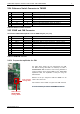
3.2.4 Reference Switch Connector to TMC429
Pin
Label
Direction
Description
1
GND
Power (GND)
Signal and system ground
2
L1
in
Input for left reference/limit switch of motor 0
3
R1
in
Input for right reference/limit switch of motor 0
4
L2
in
Input for left reference/limit switch of motor 1
5
R2
in
Input for right reference/limit switch of motor 1
6
L3
in
Input for left reference/limit switch of motor 2
7
R3
in
Input for right reference/limit switch of motor 2
Table 3.6: Reference switch connector
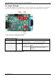
3.2.5 RS485 and CAN Connector
The standard TMCM-1110 stepRocker uses the RS485 interface pins, only.
Pin
Label
Direction
Description
1
2
3
CAN_L
bi-directional
Differential CAN bus signal (inverting) - retro-fit option
4
CAN_H
bi-directional
Differential CAN bus signal (non-inverting) - retro-fit option
5
GND
Power (GND)
Signal and system ground
6
RS485+
bi-directional
Differential RS485 bus signal (non-inverting)
7
RS485-
bi-directional
Differential RS485 bus signal (inverting)
8
9
10
Table 3.7: RS485/CAN connector
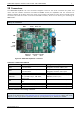
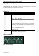
3.2.5.1 Prepare the stepRocker for CAN
CAN transceiver
SN65HVD1050D
Housing: SOIC8
0.1µF capacitor
Housing: 0603
The table above shows the pin configuration for CAN,
too. Before starting with CAN it is necessary to solder a
SN65HVD1050D CAN transceiver with housing SOIC8 and
a 0.1µF capacitor with housing 0603 on the TMCM-1110
stepRocker. Now, the stepRocker is ready for using the
CAN interface.
Because of the pin assignment CAN and RS485 can be
used at the same time.
Use firmware version V1.03 or higher with CAN interface!
It is not necessary to remove the RS485 transceiver.