
User manual


TMCM-1110 stepRocker Hardware Manual (Ref. 1.08 / 2012-APR-04) 6
www.trinamic.com
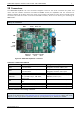
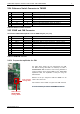
3.2.1 Power Connector
Take care of the polarity, wrong polarity can destroy the board!
Pin
Label
Direction
Description
1
GND
Power (GND)
Common system supply and signal ground
2
10… 30V
Power (input)
Power supply voltage.
Table 3.2: Power connector
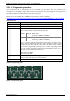
3.2.2 I/O Connector to S3FN41F
Pin
Label
Direction
Description
1
GND
Power (GND)
Supply and signal ground
2
GND
Power (GND)
Supply and signal ground
3
PWMD_0
in/out
General purpose I/O (+5V compatible, default: input)
4
PWMU_0
in/out
General purpose I/O (+5V compatible, default: output)
5
PWMD_1
in/out
General purpose I/O (+5V compatible, default: input)
6
PWMU_1
in/out
General purpose I/O (+5V compatible, default: output)
7
PWMD_2
in/out
General purpose I/O (+5V compatible, default: input)
8
PWMU_2
in/out
General purpose I/O (+5V compatible, default: output)
9
AIN_0
in
Analog input (can be used as home switch)
input voltage range: 0… +10V,
resolution: 12bit (0… 4095)
10
PHASE_A
in
Encoder input channel A
(+5V compatible, internal pull-up to +5V)
11
OpenDrain_1
out
Open-drain output (max. 100mA)
12
PHASE_B
in
Encoder input channel B
(+5V compatible, internal pull-up to +5V)
13
OpenDrain_2
out
Open-drain output (max. 100mA)
14
PHASE_Z
in
Encoder input zero channel
(+5V compatible, internal pull-up to +5V)
Table 3.3: I/O connector S3FN41F
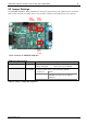
3.2.3 Motor Connector
The motor is connected at the motor connector, one phase (phase A) between A1 and A2 and the second phase
(phase B) between B1 and B2.
Do not connect or disconnect the motor while the board is powered as this can destroy the transistors!
Pin
Label
Direction
Description
1
A1
out
Pin 1 of motor coil A
2
A2
out
Pin 2 of motor coil A
3
B1
out
Pin 1 of motor coil B
4
B2
out
Pin 2 of motor coil B
Table 3.5: Motor connector