
User manual


TMCM-1110 stepRocker Hardware Manual (Ref. 1.08 / 2012-APR-04) 5
www.trinamic.com
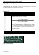
3.2 Connectors
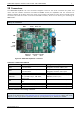
The TMCM-1110 stepRocker has nine connectors altogether. There are two screw connectors for power and
motor and two interface connectors (mini-USB and RS485). Further, the stepRocker has one connector for
reference switches for all three motors, the driver input connector (TTL level) for motor 0, two controller output
connectors (TTL level) for motors 1 and 2 and the GPIO connector, which can be used e.g. for connecting an
ABN-encoder.
Start with power supply OFF and do not disconnect the motor while the board is powered as this can
destroy the transistors!
Power
Motor
Reference
switches
Controller
Out 2
Controller
Out 1
GPIO Driver In 0
USB
RS485
(CAN
optional)
1
1
14
1
1 11
1
1
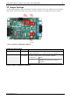
Figure 3.2: TMCM-1110 stepRocker connectors
CONNECTORS OF TMCM-1110 STEPROCKER
Label
Connector type
Mating connector type
Power
RIA 220-02, 2 pol., 5.08mm pitch,
shrouded header
RIA 249-02, screw type terminal block,
pluggable, centerline 5.08mm pitch
Motor
RIA 183-04, 4 pol., 3.5mm pitch,
shrouded header
RIA 169-04, screw type terminal block,
pluggable, centerline 3.5mm pitch
USB
USB-mini female connector
USB-mini male connector
RS485/CAN
Low profile box header without locking
bar, type 8380, 10 pol., DIN 41651,
2.54mm pitch
Low profile IDC socket connector, 10pol.,
DIN41651, 2.54mm pitch
GPIO
Multi-pin-connector, 14 pol., 2.54mm
pitch
Female connector with 2.54mm pitch
Ref. switches
Multi-pin-connector, 7 pol., 2.54mm pitch
Female connector with 2.54mm pitch
Driver In
Multi-pin-connector, 3 pol., 2.54mm pitch
Female connector with 2.54mm pitch
Controller Out 1, 2
Multi-pin-connector, 3 pol., 2.54mm pitch
Female connector with 2.54mm pitch
Table 3.1: Connectors and mating connectors
Because of the characteristic of the TMCM-1110 stepRocker as development platform TRINAMIC offers its
internal circuit diagram here: www.steprocker.com or www.motioncontrol-community.org. Please refer to the
diagram in order to get further information about the pin assignments of µC, TMC429, and TMC262.