MODULE FOR STEPPER MOTORS MODULE Hardware Version V1.1 HARDWARE MANUAL + + 1-axis stepper controller / driver module 1A RMS / 2.8A RMS 24V DC USB, RS485 + + UNIQUE FEATURES: TRINAMIC Motion Control GmbH & Co. KG Hamburg, Germany www.trinamic.
TMCM-1110 stepRocker Hardware Manual (Ref. 1.08 / 2012-APR-04) Table of Contents 1 2 3 4 5 6 7 8 Features ........................................................................................................................................................................... 3 Order Codes ................................................................................................................................................................... 4 Mechanical and Electrical Interfacing ............
TMCM-1110 stepRocker Hardware Manual (Ref. 1.08 / 2012-APR-04) 3 1 Features The TMCM-1110 stepRocker is a single axis motor controller/driver board for 2-phase bipolar stepper motors. It features the TRINAMIC controller/driver chain consisting of TMC429 and TMC262 in combination with a Samsung S3FN41F processor. The Module is intended to be a fully functional development platform.
TMCM-1110 stepRocker Hardware Manual (Ref. 1.08 / 2012-APR-04) 4 2 Order Codes The standard version of the stepRocker has RS485 interface and USB interface. The module is pre-programmed with TRINAMICs TMCL™ Firmware with all available features. For developing one’s own firmware please refer to www.steprocker.com or www.motioncontrol-community.org.
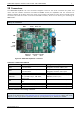
TMCM-1110 stepRocker Hardware Manual (Ref. 1.08 / 2012-APR-04) 5 3.2 Connectors The TMCM-1110 stepRocker has nine connectors altogether. There are two screw connectors for power and motor and two interface connectors (mini-USB and RS485). Further, the stepRocker has one connector for reference switches for all three motors, the driver input connector (TTL level) for motor 0, two controller output connectors (TTL level) for motors 1 and 2 and the GPIO connector, which can be used e.g.
TMCM-1110 stepRocker Hardware Manual (Ref. 1.08 / 2012-APR-04) 6 3.2.1 Power Connector Take care of the polarity, wrong polarity can destroy the board! Pin 1 2 Label GND 10… 30V Direction Description Power (GND) Common system supply and signal ground Power (input) Power supply voltage. Table 3.2: Power connector 3.2.
TMCM-1110 stepRocker Hardware Manual (Ref. 1.08 / 2012-APR-04) 7 3.2.
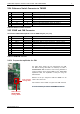
TMCM-1110 stepRocker Hardware Manual (Ref. 1.08 / 2012-APR-04) 8 3.2.6 USB Connector A USB interface is available via a mini-USB connector. This module supports USB 2.0 Full-Speed (12Mbit/s) connections. Pin 1 2 3 4 5 Label VBUS Direction Power (+5V input) bi-directional bi-directional DD+ ID GND Power (GND) Description +5V supply from host USB Data USB Data + Connected to signal and system ground Signal and system ground Table 3.9: USB connector 3.2.
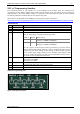
TMCM-1110 stepRocker Hardware Manual (Ref. 1.08 / 2012-APR-04) 9 3.2.9 µC Programming Interface The programming pads of the interface are on the backside of the module. There are possibilities for programming in two different modes: debug mode and serial writing mode. The selection of the programming mode depends on the chosen adapter. Further, it is possible to use the programming pads of the µC interface by soldering adequate contacts directly on the programming pads.
TMCM-1110 stepRocker Hardware Manual (Ref. 1.08 / 2012-APR-04) 10 3.3 Jumper Settings The TMCM-1110 stepRocker offers possibilities for settings by jumper. Here, three adjustments are mentioned. Select motion controller and select motor current are basic. Jumpers on the GPIO connector are optional. Select motion controller Select motor current Select motor current Figure 3.3: Jumper of TMCM-1110 stepRocker TMCM-1110 STEPROCKER JUMPERS Jumper Label Select motor current 1A/2.
TMCM-1110 stepRocker Hardware Manual (Ref. 1.08 / 2012-APR-04) 11 3.4 LEDs LEDS OF THE TMCM-1110 STEPROCKER Status Power on Label POWER Description This orange LED lights up upon the power supply is working. LED1 without defined function LED1 This yellow LED is applicable and can be used customer specific. The LED is connected to pin 59 of the S3FN41F microcontroller. LED2 without defined function LED2 This yellow LED is applicable and can be used customer specific.
TMCM-1110 stepRocker Hardware Manual (Ref. 1.08 / 2012-APR-04) 12 3.5 Communication 3.5.1 RS485 For remote control and communication with a host system the TMCM-1110 provides a two wire RS485 bus interface. For proper operation the following items should be taken into account when setting up an RS485 network: 1. BUS STRUCTURE: The network topology should follow a bus structure as closely as possible. That is, the connection between each node and the bus itself should be as short as possible.
TMCM-1110 stepRocker Hardware Manual (Ref. 1.08 / 2012-APR-04) 13 3.5.2 USB For remote control and communication with a host system the TMCM-1110 stepRocker provides a USB 2.0 fullspeed (12Mbit/s) interface (mini-USB connector). As soon as a USB-Host is connected the module will accept commands via USB.
TMCM-1110 stepRocker Hardware Manual (Ref. 1.08 / 2012-APR-04) 14 4 Functional Description The TMCM-1110 stepRocker is a highly integrated 1-axes controller/driver module. The TMCM-1110 can be controlled via RS485 or USB serial interfaces (CAN retro-fit option). The TMCM-1110 comes with the PC based software development environment TMCL-IDE for the Trinamic Motion Control Language (TMCL™).
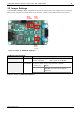
TMCM-1110 stepRocker Hardware Manual (Ref. 1.08 / 2012-APR-04) 15 4.1 Extensions of the TMCM-1110 stepRocker The TMCM-1110 stepRocker provides the possibility for extension to full 3-axis systems. The stepRocker itself can be used as master or slave. An example for extensions is shown below. GPI /O USB TMCL™ Master / Motor 0 S/D OUT 3 x REF- IN USB / RS485 only initialization and parameterization USB / RS485 only initialization and parameterization S/D IN Motor 1 S/D IN Motor 2 Figure 4.
TMCM-1110 stepRocker Hardware Manual (Ref. 1.08 / 2012-APR-04) 16 5 Operational Ratings The operational ratings show the intended or the characteristic ranges and should be used as design values. In no case shall the maximum values be exceeded.
TMCM-1110 stepRocker Hardware Manual (Ref. 1.08 / 2012-APR-04) 6 Life Support Policy TRINAMIC Motion Control GmbH & Co. KG does not authorize or warrant any of its products for use in life support systems, without the specific written consent of TRINAMIC Motion Control GmbH & Co. KG.
TMCM-1110 stepRocker Hardware Manual (Ref. 1.08 / 2012-APR-04) 7 Revision History 7.1 Document Revision Author Version Date 1.00 1.01 1.02 1.03 1.04 2011-OCT-01 2011-OCT-04 2011-OCT-05 2011-OCT-27 2011-OCT-31 SD GG SD SD SD 1.05 2011-DEC-21 SD 1.06 1.07 2011-DEC-22 2012-JAN-03 SD SD 1.08 2012-APR-04 SD SD – Sonja Dwersteg GG – Guido Gandolfo Description First version Minor changes Minor changes Minor changes Minor changes - Chapter 3.2.