
Installation Manual
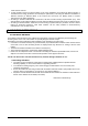
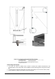
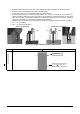
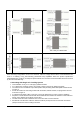
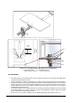
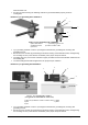
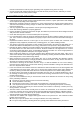
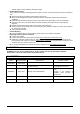
Table Of Contents
- 1. DISCLAIMER OF LIABILITY .............................................................................................................. - 3 -
- 5.1 CLIMATE CONDITIONS
- 5.2 SITE SELECTION
- 6.1 MOUNTING METHODS
- B. Mounting with Clamps
- C. Mounting with Single-axis Tracking System
- 6.2 GROUNDING
- 6.3 MODULE WIRING
- 7.1 FUSING
- 7.2 INVERTER SELETION AND COMPATIBILITY

Date: 2018.7.16
Doc No: PS-M-0434
Ver. D
Page - 13 - of 17
•
•
•
•
•
•
•
•
•
www.trinasolar.com.
• We also recommend using the following methods to ground installation properly under UL
investigation,
Method 1: Tyco grounding bolt # 2058729-1:
Figure 4. Tyco grounding bolt # 2058729-1
1) Wire bolt and slot 2) Mounting wash hex nut
3) Aluminum frame 4) 0.006 to 0.025in
2
cable
5) Hex Nut
• Tyco grounding hardware comes in a package that includes the grounding bolt, mounting and
grounding hex nut.
• Electrical contact is made by penetrating the anodized coating of the aluminum frame, and tightening
the mounting hex nut (come with the star washer) to the proper torque of 25lbf.in.
• Grounding wire size (6 to 12 AWG solid bare copper) should be selected and installed underneath the
wire binding bolt.
• The wire binding bolt should be tightened to the proper torque of 45lbf.in.
Method 2: Tyco grounding bolt #1954381-2:
2
1 3
4
5
Figure 5. Tyco grounding bolt # 1954381-2
(Not applicable for TRINAMOUNT module series)
1) Wire slot (available for 0.006 to 0.025in
2
cable) 2) Slider
3) Bolt 4) Base
5) Nut
• Tyco grounding hardware comes in a package that includes the grounding bolt, mounting and
grounding hex nut.
• Electrical contact is made by penetrating the anodized coating of the aluminum frame, and tightening
the mounting hex nut (come with the star washer) to the proper torque of 25lbf.in.
1
2
3
4
5