
TrinaSolar Installation


5
• Tyco Grounding hardware is a package that includes the grounding bolt, mounting and grounding hex nut .
• Make electrical contact by penetrating the anodized coating of the aluminum frame, by tightening the The
mounting wash hex nut(come with the star washer) to the proper torque (25 in lb.)
• Select grounding wire size: (6 to 12 AWG solid bare copper) and install underneath wire binding bolt.
• Tighten wire binding bolt to proper torque (45 in lb).
• The Tyco grounding bolt is only UL listed for use with 6-12 AWG bare solid copper wire.
6.3 MODULE WIRING
Each module has two standard 90°C sunlight resistant output cables each terminated with plug & play
connectors. The wire type and gauge of the output cables are 600V rated PV Wire cable and are 12AWG in size.
This cable is suitable for applications where wiring is exposed to the direct sunlight. We required that all wiring and
electrical connections comply with the appropriate national electrical code.
For field connections, use the minimum 12AWG copper wires insulated for a minimum of 90°C and Sunlight
resistance with insulation designated as PV Wire.
• The minimum and maximum outer diameters of the cable are 5 to 7mm
2
.
7. MAINTENANCE AND CARE
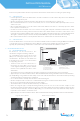
• Under most weather conditions, normal rainfall is sufficient to keep the PV module glass surface clean. If dust or dirt
build-up becomes excessive, clean the glass only with a soft cloth using mild detergent and water.
• Do not clean the modules with cold water during the warmer hours of the day in order to avoid creating any thermal
shock that may damage the module.
• Be cautious when cleaning the back surface of the module to avoid penetrating the substrate material. Modules that
are mounted flat (0° tilt angle) should be cleaned more often, as they will not ''self clean'' as effectively as modules
mounted at a 15° tilt or greater.
• At least once a year, it is recommended to check the torque of terminal screws and the general condition of wiring.
Also, check that mounting hardware is properly torqued. Loose connections will result in damage for the array.
• Modules that have been replaced must be of same type. Do not touch live parts of cables and connectors. Use
appropriate safety equipment (insulated tools, insulating gloves, etc.) when handling modules.
• Cover the front surface of modules by an opaque material when repairing. Modules when exposed to sunlight
generate high voltage and are dangerous.
Trina Solar SPV modules are equipped with bypass diodes in the junction box. This minimizes module heating and
current losses.
• Do not try to open the junction box to change the diodes even if it malfunctions.
• In a system that uses a battery, blocking diodes are typically placed between the battery and the SPV module output
to prevent battery discharge at night.
WARNING: For any electrical maintenance, the PV system must rst be shut down. Improper maintenance
can cause lethal electric shock and/or burns.
INSTALLATION MANUAL
UL 1703 version