
TrinaSolar Installation


4
Note:
• Clearance between modules frames and surface of the wall or roof is required to prevent wiring damage and to
allow air to circulate behind the module. Recommended stand-off height is 115mm.
• Do not mount SPV modules in such way that drain holes of modules are blocked.
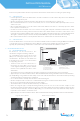
We recommend to use the landscape and portrait orientation to install the module, Please note the diagram below
when install:
6.2 GROUNDING
• All module frames and mounting racks must be properly grounded in accordance with appropriate respective
national electrical code.
• Proper grounding is achieved by bonding the module frame(s) and all metallic structural members together
continuously using a suitable grounding conductor. Grounding conductor or strap may be copper, copper alloy,
or other material acceptable for use as an electrical conductor per respective National Electrical Codes. The
grounding conductor must then make a connection to earth using a suitable earth ground electrode.
• We recommend to use the following methods to ground properly:
INSTALLATION MANUAL
UL 1703 version
1/20 Module Width
Mounting
Area
Mounting
Area
1/5 Module Width
1/5 Module Width
1/20 Module Width
Mounting
Area
Mounting
Area
1/8 Module Width
1/4 Module Width
1/4 Module Width
1/8 Module Width
Figure3. Mechanical dimensions when modules installed at lorientation with Clamp fitting method
Figure4. Mechanical dimensions when modules installed in portrait orientation with clamp fitting method
Figure5. Tyco grounding bolt # 2058729-1
1
2
4
5
3
1) Wire bolt and slot
2) Mounting wash hex nut
3) Aluminum frame
4) 6-12 AWG cable
5) HEX Nut