
TrinaSolar Installation


3
Professional system installer must be responsible for mechanical load calculation according to system design.
5.2 SITE SELECTION
• In most applications, Trina Solar SPV modules should be installed in a location where they will receive maximum
sunlight throughout the year.
• Modules should not be shaded at any time of the day because of buildings, trees, chimney, etc.
• Do not install SPV modules in corrosive environment, such as corrosive salt areas within proximity of the ocean or
sulfurous area, etc.
• Do not install SPV modules in a location where it would be immersed in water or continually exposed to water
from a sprinkler or fountain, etc.
• modules should be mounted over a fire resistant covering, with adequate ventilation between the module
backsheet and the mounting surface. Clearance between the module frames and surface of the wall or roof is
required to prevent wiring damage and to allow air to circulate behind the module. The required minimal stand-
off height is 115mm. Any slope less than 5in/ft (127mm/305mm) is required to maintain a fire class rating.
• Do not mount SPV module in such way that the drain holes of SPV module are intended to block up.
5.2 SITE SELECTION
Trina Solar SPV modules connected in series should be installed at same orientation and angle. Different orientation
or angle may cause loss of output power due to difference of amount of sunlight exposed to the module.
Typically, the optimal tilting of SPV module is almost the same as the latitude of installation location.
6. MOUNTING INSTRUCTIONS
6.1 MOUNTING METHODS
PV modules can be mounted to the
substructure using the following methods:
(1) Screw fitting: Using corrosion-proof screws
(M8) in the existing installing holes in the
module frame. The frame of each module has
4 mounting holes used to secure the modules
to supporting structure.
• Module frame must be attached to a
mounting rail using M8 corrosion-proof
screws together with spring washers and flat
washers in four symmetrical locations on the
SPV module.
• The modules have been evaluated by for mounting using the 4 provided mounting holes in the frame.
• Applied torque should be 8 Newton-meters. Please find detailed mounting information in the below illustration:
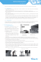
(2) Clamp fitting: Using suitable module clamps on the side of the module frame to mount the modules (including
“portrait orientation” and “landscape orientation”)
• Use a certain number of clamps to fix modules on the mounting rail.
• Modules clamps should not come into contact with the front glass and must not deform the frame.
• Be sure to avoid shadowing effects from the module clamps.
• The module frame is not to be modified under any circumstances.
• When choosing this type of clamp-mounting method, please be sure to use at least four clamps on each
module, two clamps should be attached on the long sides of the module (for portrait orientation) and short sides
of the module (for landscape orientation). Depending on local wind and snow loads, additional clamps may be
required to ensure modules can bear the load.
• Applied torque should be 8 Newton-meters. Please find detailed mounting information in the below illustration
Fringe modules installation Middle modules installation
INSTALLATION MANUAL
UL 1703 version
Figure1. SPV module installed with Screw fitting method
1) Aluminum Frame
3) Flat Stainless Washer
5) HEX Stainless Nutt
2) M8 Stainless screw
4) Spring Stainless Washer
1
2
3
4
5
Figure2. SPV module installed with clamp fitting method
*