
Trina Allmax M Plus Solar Module Installation Manual (IEC-UL)
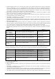
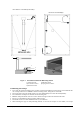
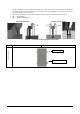
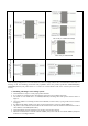
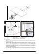
Table Of Contents

Date: April, 2016 DOC: PS-M-0434 A Page - 9 - of 15
Clamping system
Attachment to the long frame
This is Only for TSM-DC03A.08(II)
This is Only for TSM-PC05B
Clamping system
Attachment to the short frame
Other mounting configurations can be used. However, failure to comply with the above recommendations will result in a
lowering of the load handling (snow/wind load) capabilities below the product specification 5400/2400Pa(IEC),
5400/3800Pa(UL1703) and product failure as a result of an overload situation will not be covered by the Trina Solar
warranty.
C. Mounting with Single-axis Tracking System:
• This installation is only for 72 cells polycrystalline modules.
• It is a Single-axis Tracking System, the module is fixed on the axis by bolting long frame.
• The frame of each module has 4-φ7*10mm(0.28*0.39in) mounting holes with specific location shown in
Figure 3.
• Secure the module in each fixing location with an M6 bolt, two flat washers, a spring washer and nut as shown
in Figure 3.
• If a different bolt similar to M6 is used, they need to be tightened to a torque of 16N.m.(140lbf.in).
• All parts in contact with the frame should use flat stainless steel washers of minimum 1.5mm thickness with an
outer diameter of 16-20mm(0.63-0.79in.).
• The bolt should be made of stainless steel or the other anti-corrosion material.
• Mechanical Load Pressure under this method: 2400Pa (snow) max from the front side & 2400Pa (wind) max
from the rear according to UL1703.