
Trina Allmax M Plus Solar Module Installation Manual (IEC-UL)
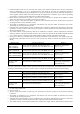
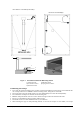
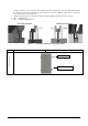
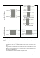
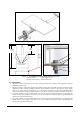
Table Of Contents

Date: April, 2016 DOC: PS-M-0434 A Page - 8 - of 15
should be attached on each long sides of the module (for portrait orientation) or each short sides of the module
(for landscape orientation). Depending on local wind and snow loads, additional clamps may be required to
ensure that modules can bear the load.
• Applied torque should refer to mechanical design standard according to the bolt customer is using, ex:
• M6 ---- 9 N.m(70lbf.in)
• M8 ---- 16-20N.m(140-180lbf.in)
Figure 2. PV module installed with clamp fitting method
±2400Pa Load
+5400Pa/-2400Pa Load
Mounting system
End Clamp installation
Middle Clamp installation
Mounting rail
4-
φ
9*12 installation hole