
Trina Allmax M Plus Solar Module Installation Manual (IEC-UL)
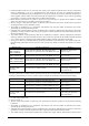
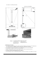
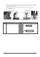
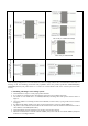
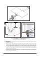
Table Of Contents

Date: April, 2016 DOC: PS-M-0434 A Page - 6 - of 15
max under UL1703 standard)
*Notes:
-The modules have been evaluated by TUV according to IEC61215 for a maximum positive or negative design
loading of below 550Kg/m² (5400Pa),by UL according to UL 1703, below 30lbs.ft
2
.
-The mechanical load bearing is dependent upon the mounting methods used and failure to follow the instructions
of this manual may result in different capabilities to withstand snow and wind loads.
-The system installer must ensure that the installation methods used meet these requirements and any local codes
and regulations.
5. SITE SELECTION
• Trina Solar Modules can be mounted in landscape or portrait orientation however the impact of dirt shading the
solar cells can be minimized by orienting the product in landscape.
• Solar module is recommended to be installed at an optimized tilt angle to maximize the energy output. It is roughly
equal to the latitude of the project site as a rule of thumb, facing to equator. But always to design based on local
situations to find out the optimum one.
• When installing solar modules on a roof always leave a safe working area between the edge of the roof and the
external edge of the solar array.
• In case of residential installations on the ground, modules shall be installed following local regulations, e.g. using
fence.
• Position the modules to minimize the chances of shading at any time of the day.
• Do not install PV modules in a location where they will be immersed in water or continually exposed to water from
a sprinkler or fountain, etc.
• Avoid using a mounting method that will block the drainage holes in the module frame.
• When all solar modules (except for smart module) are mounted in the same plane and orientation then all can be
expected to have similar performance throughout the day and can be connected together to the same inverter
channel.
• If solar modules (except for smart module) on the same installation are mounted at different angles or orientations
then energy production can normally be optimized by connecting the different orientations to different inverters (or
different MPPT if the inverter has more than one MPPT). Refer to inverter manufacturers for further guidelines.
• According to Intertek-conducted IEC 61701:2011, salt mist corrosion testing of photovoltaic (PV), Trina Solar
modules can be safely installed in corrosive salt areas within proximity of the ocean or sulfurous areas.
• According to IEC62716:2013 “Ammonia corrosion testing of photovoltaic (PV) modules” and DLG Fokus testing
for ammonia resistance, Trina Solar modules can be safely installed in ammonia-heavy environments, such as farm
houses.
6. MOUNTING INSTRUCTIONS
6.1 MOUNTING METHODS
PV modules can be mounted to the substructure using either corrosion-proof M8 bolts placed through the mounting
holes on the rear of the module or specially designed module clamps.
Regardless of the fixing method the final installation of the modules must ensure that:
• A clearance of at least 115mm(4.5in) (recommended) is provided between modules frame and the surface of the
wall or roof. If other mounting means are employed this may affect the UL Listing or the fire class ratings.
• The minimum distance between two modules is 10mm(0.4in).
• The mounting method does not block the module drainage holes.
• Panels are not subjected to wind or snow loads exceeding the maximum permissible loads, and are not subject
to excessive forces due to the thermal expansion of the support structures.
Note: The drain holes cannot be blocked in any situation during installation or use.
A. Mounting with Bolts
The frame of each module has 4-φ9*12mm mounting holes, ideally placed to optimize the load handling
capability, to secure the modules to supporting structure.
• To maximize mounting longevity, Trina Solar strongly recommends the use of corrosion proof (stainless steel)
fixings
• Secure the module in each fixing location with an M8 bolt and a flat washer, spring washer and nut as shown in
Figure 1 and tighten to a torque of 16~20 N.m(140-180lbf.in.).
• All parts in contact with the frame should use flat stainless steel washers of minimum 1.8mm thickness with an