
Trina Allmax M Plus Solar Module Installation Manual (IEC-UL)
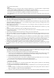
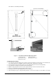
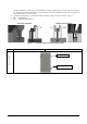
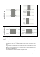
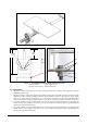
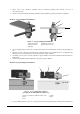
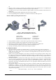
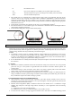
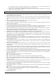
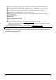
Table Of Contents

Date: April, 2016 DOC: PS-M-0434 A Page - 13 - of 15
N No modules in series
Voc Open circuit voltage of each module (refer to product label or data sheet)
TCvoc Thermal coefficient of open circuit voltage for the module (refer to data sheet)
Tmin The lowest ambient temperature
• Each module have two standards 90°C sunlight resistant output cables each terminated with plug & play
connectors. The wire type and gauge of the output cables are 1000V (For TSM-PE05A.**, PE14A.** which are
1500V DC) rated PV Wire cable and are 12AWG in size. This cable is suitable for applications where wiring is
exposed to the direct sunlight. We require that all wiring and electrical connections comply with the appropriate
National Electrical Code.
• The minimum and maximum outer diameters of the cable are 5 to 7mm(0.038 to 0.076in
2
).
• For field connections, use at least 4mm
2
copper wires insulated for a minimum of 90°C and sunlight resistance
with insulation designated as PV Wire.
• The minimum bending radius cables should be 43mm(1.69in).
7. ELECTRICAL CONFIGURATION
Photovoltaic (electric) systems operate automatically and require very little day-to-day supervision. The solar array
generates DC electricity whenever light falls on it similarly the inverter automatically turns ON as soon as there is
sufficient energy from the solar array to efficiently convert this into grid.
*Caution:
• The module is rated to operate at potentially lethal DC voltages which have the potential can cause severe
electrical shock, arcing and fire hazards. Whilst some solar modules, manufactured by Trina Solar, are certified
to operate up to 1000V DC (For TSM-PE05A.**,PE14A.**, to 1500V DC) always check the module label to
confirm the actual rating of your product before making connections.
• It is recommended to use a suitably rated isolator (DC switch) to interrupt the current flow before disconnecting
the connectors.
7.1 FUSING
• When fuses are fitted they should be rated for the maximum DC voltage and connected in each, non-grounded
pole of the array (i.e. if the system is not grounded then fuses should be connected in both the positive and
negative poles).
• The maximum rating of a fuse connected in series with an array string is typically 15A but the actual module
specific rating can be found on the product label and in the product datasheet.
• This fuse rating value also corresponds to the maximum reverse current that a module can withstand (when one
string is shaded then the other parallel strings of modules will be loaded by the shaded string and current will
flow) and therefore impacts the number of strings in parallel.
7.2 INVERTER SELETION AND COMPATIBILITY
• When installed in systems governed by IEC regulations, Trina Solar modules normally do not need to be
electronically connected to earth and therefore can be operated together with either galvanically isolated (with
transformer) and transformerless inverters.
• Potential Induced Degradation (PID) is sometimes observed in PV modules due to a combination of high
humidity, high temperature and high voltage. PID is most likely to cause degradation under the following
conditions:
a) Installations in the warm and humid climates
b) Installation close to a source of continual moisture, such as bodies of water
• To reduce the risk of PID, we strongly suggest that modules feature Trina Solar’s Anti-PID technology, which
Incorrect Routing of cable
Correct Routing of cable