
Trina Allmax M Plus Solar Module Installation Manual (IEC-UL)
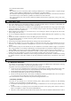
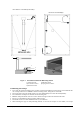
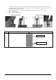
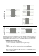
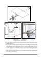
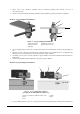
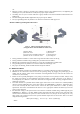
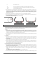
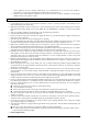
Table Of Contents

Date: April, 2016 DOC: PS-M-0434 A Page - 12 - of 15
nut.
• Electrical contact is made by penetrating the anodized coating of the aluminum frame, and tightening the
mounting hex nut (come with the star washer) to the proper torque of 25lbf.in.
• Grounding wire size (6 to 12 AWG solid bare copper) should be selected and installed underneath the wire
binding bolt.
• The wire binding bolt should be tightened to the proper torque of 45lbf.in.
• The Tyco grounding bolt is only listed for use with 6 to 12 AWG bare solid copper wire.
Method 3: ERICO grounding bolt # EL6CS14-6
1) Machine Bolt A 2) Machine Bolt B
3
) Belleville washer 4) Flat Washer
5) Clearance hole for #10[M5] machine bolt 6) Aluminum frame
7) Machine box hex nut with lock washer 8) Grounding bolt
• The lug should be installed on a surface that is larger than the bottom surface of the lug.
• The lug should be installed in the grounding holes provided on the PV module.
• Machine bolt A should be torqued to 35lbf.in, to secure the grounding bolt to module frame.
• The grounding bolt is only listed for use with 6-12 AWG bare solid copper wire.
• For proper wire binding, machine bolt B should be torqued to 35lbf.in.
6.3 MODULE WIRING
• All wiring should be performed, by qualified installers, in accordance with the local codes and regulations.
• Modules can be connected in series to increase the operating voltage by plugging the positive plug of one
module into the negative socket of the next. Before connecting modules always ensure that the contacts are
corrosion free, clean and dry.
• Product can be irreparably damaged if an array string is connected in reverse polarity to another. Always verify
the voltage and polarity of each individual string before making a parallel connection. If you measure a
reversed polarity or a difference of more than 10V between strings then check the string configuration before
making the connection.
• Trina Solar modules are provided with stranded copper cables with a cross sectional area of 4mm²(0.006in²)
which are rated for 1000V DC, 90°C and are UV resistant.( For TSM-PE05A.**, PE14A.**, 1500 V DC, 90°C
and are UV resistant) All other cables used to connect the DC system should have a similar (or better)
specification. Trina Solar recommend that all cables are run in appropriate conduits and sited away from areas
prone to water collection.
• The maximum voltage of the system must be less than the maximum certified voltage 1000V typically (For
TSM-PE05A.**, PE14A.** , less than 1500V) and the maximum input voltage of the inverter and of the other
electrical devices installed in the system. To ensure that this is the case, the open circuit voltage of the array
string needs to be calculated at the lowest expected ambient temperature for the location. This can be done
using the following formula.
Max System voltage ≥ N * Voc * [1 + TCvoc x (Tmin-25)]
Where
Figure 6. ERICO grounding bolt # EL6CS14-6
(Not applicable for the TRINAMOUNT module series)