
User's Manual Part 2

14
XDL Micro Intergrator’s Guide
Mechanical Considerations
EMI interferers
The transceiver is easily mounted in new and existing products. The transceiver is
specifically designed for operation in harsh environments. For best performance, mount
the radio away from potential EMI radiators and route RF signals apart from digital
signals.
CAUTION – To avoid interference between the signals, Pacific Crest recommends you do not
bundle the antenna interface cable with other signal cables internal to your product.
Shock and vibration
Sensitive receivers, such as that in the XDL Micro transceiver, are susceptible to
interference due to mechanical shock and vibration. To reduce the potential for
electromechanical interference, you must use a robust mounting scheme when you
integrate the transceiver into other systems. You may need to use a thin damping pad
between the mounting surface and the transceiver. Pacific Crest recommends that the
damping pads you use are made of PORON® or a similar material.
Thermal transfer
The transceiver requires additional thermal heat dissipation in order to supply maximum
output power at elevated ambient temperatures and high-duty cycles. The transceiver has
a thermal sensor and a firmware controlled limit switch. To prevent permanent damage
to the transmitter, the XDL Micro module shuts down when its internal temperature
reaches 85 °C (185 °F). The integrated heat sink is adequate for most bench top testing,
but when the transceiver is integrated into other systems you must consider additional
thermal heat sinking. The transceiver produces approximately 6 Watts of heat at full RF
power out.
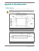
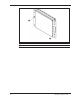
For mounting diagrams and specification, see Appendix A: Mounting Guide, page 15.
Materials
The transceiver is housed in a metal shield that is a conductor and is electrically
connected to the ground and signal ground pins.