
User's Manual Part 1

TDL 450i Intergrator’s Guide 15
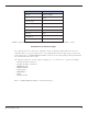
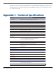
Circuit Center Frequency (MHz) Bandwidth (MHz)
First IF 54.45 0.015
Second IF 0.450 0.010
TDL 450i Frequency Plan
Mechanical Considerations
EMI interferers
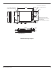
The TDL 450i transceiver is easily mounted inside new and existing products. The TDL 450i
transceiver is specifically designed for operation in harsh environments. For best performance,
mount the radio away from potential EMI radiators and route RF signals apart from digital signals.
Caution: We do not recommend the bundling of the antenna interface cable with other signal cables
internal to your product.
Shock and Vibration
Sensitive radio transceivers, such as the TDL 450i transceiver, are susceptible to interference due
to mechanical shock and vibration. To reduce the potential for electromechanical interference, a
robust mounting scheme must be used when being integrated into other systems. A thin damping
pad between the mounting surface and the TDL 450i transceiver may be required. We recommend
the use of damping pads made of PORON(R) or a similar material.
Thermal Transfer
The TDL 450i transceiver requires additional thermal heat dissipation in order to supply maximum
power out at elevated ambient temperatures and high duty cycles. The TDL 450i transceiver has
a thermal sensor and a firmware controlled limit switch. The TDL 450i will shut down when the
PCB temperature reaches 85°C to prevent permanent damage to transmitter. The integrated heat
sink is adequate for most bench top testing but when the TDL 450i transceiver is integrated into
other systems additional thermal heat sinking must be considered. The TDL 450I will produce