
User's Manual Part 1

TDL 450i Intergrator’s Guide 14
Error Codes
The TDL 450i transceiver performs a variety of power-up and run-time tests to assure optimal operation.
Tests include environmental as well as electrical measurements designed to avoid damage to the unit while
maintaining adequate operation.
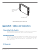
A 50Ω impedance coaxial MMCX style RF connector is provided for attachment to an external antenna
system. The MMCX connector offers a positive friction locking mechanism that is very reliable. In some
circumstances, it may be required to provide a physical stop to prevent the MMCX plug from becoming
disconnected due to extreme shock or vibration.
The TDL 450i transceiver requires an antenna and feed cable system that is impedance- matched to 50Ω.
We recommend that high quality RG-178 or equivalent coaxial cable be used for internal wiring of the RF
signal from the MMCX to the panel connector. We also suggest the selection of an antenna that has a low
VSWR (less than 1.5:1) and that has been tuned for operation in the band of the TDL 450i transceiver.
Caution: Improper impedance matching of the antenna, connectors or cable will degrade the performance of
the TDL 450i transceiver.
Shielding Considerations
The TDL 450i transceiver is designed to operate in proximity to noise generating circuitry. However, certain
radiated or conducted frequencies may degrade the performance of the TDL 450i transceiver or render it
inoperable. When possible, provide well-grounded shielding between circuits that radiate, such as power
supplies, voltage-controlled oscillators, crystal oscillators and the TDL 450i transceiver.
Frequency Planning
The TDL 450i transceiver contains a very sensitive, dual-conversion super-heterodyne receiver.
Caution: Radiated and conducted signals to and from the TDL 450i transceiver may cause problems due to
interference. Proper attention to frequency planning may reduce interference from radiated or conducted
frequencies that fall within the pass-bands of the filters at the IF frequencies.
We recommend the use of upfront analysis of the product frequency plan (including harmonics) and then
the use of a spectrum analyzer to determine the potential for interference within the pass-bands of the
various front-end and band pass filters.
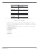
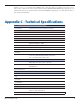
The following table indicates the frequencies and band pass filter characteristics that are areas of potential
interference.
Circuit Center Frequency (MHz) Bandwidth (MHz)
RF front-end 438 70