
User's Manual
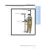
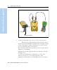
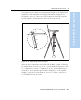
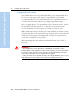
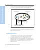
Table Of Contents
- Safety Information
- Introduction
- Trimble R7 GPS Receiver
- Overview
- Setting up the Receiver
- General Operation
- Configuration
- Transferring Data
- Software Utilities
- Specifications
- Default Settings
- Cables and Connectors
- Event Marker Input and 1PPS Output
- Trimble R8 GPS Receiver
- Overview
- Setting up the Receiver
- General Operation
- Configuration
- Software Utilities
- Specifications
- Default Settings
- Cables and Connectors
- Appendixes Trimble R7 / Trimble R8
- NMEA-0183 Output
- RTCM Output
- Troubleshooting
- Index

Trimble R7/R8 GPS Receiver User Guide 35
Setting up the Receiver 3
Trimble R7 GPS Receiver Operation
Use Figure 3.14 as a guide for measuring the height of the Zephyr and
Zephyr Geodetic antennas. The Zephyr antenna is designed to be
measured to the top of the notch. The Zephyr Geodetic (shown) has
been designed to be measured to the bottom of the notch.
Figure 3.14 Measuring antenna height
Older models of antennas, such as the Choke Ring or Micro-Centered™
L1/L2 antennas, need more power to operate than the Zephyr models.
To configure the receiver to output more power on the antenna port,
select the correct antenna type in GPS Configurator, or through the
Trimble controller. For information on how to do this, contact your
local Trimble Service Provider.
1.520
1.510
1.515
1.505