
User's Manual
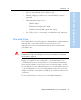
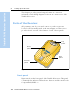
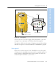
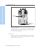
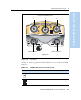
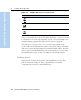
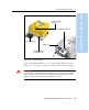
Table Of Contents
- Safety Information
- Introduction
- Trimble R7 GPS Receiver
- Overview
- Setting up the Receiver
- General Operation
- Configuration
- Transferring Data
- Software Utilities
- Specifications
- Default Settings
- Cables and Connectors
- Event Marker Input and 1PPS Output
- Trimble R8 GPS Receiver
- Overview
- Setting up the Receiver
- General Operation
- Configuration
- Software Utilities
- Specifications
- Default Settings
- Cables and Connectors
- Appendixes Trimble R7 / Trimble R8
- NMEA-0183 Output
- RTCM Output
- Troubleshooting
- Index

3 Setting up the Receiver
16 Trimble R7/R8 GPS Receiver User Guide
Trimble R7 GPS Receiver Operation
The power/serial data ports are all 7 pin 0-shell Lemo connectors. Both
Port 2 and Port 3 can accept external power. For more information, see
Default Settings, page 80 and Cables and Connectors, page 87.
The TNC port connectors are color-coded for easy system setup.
Connect the yellow GPS antenna cable to the yellow TNC port marked
GPS, and connect the blue Range Pole antenna (RPA) cable to the blue
TNC connector marked RADIO. For more information on connecting
the Trimble R7 receiver, see the following sections in this chapter.
31.4 Bottom panel
Figure 3.5 shows the bottom panel of the Trimble R7 receiver. This
panel contains the USB port, the CompactFlash port, and the
compartments for the two internal batteries.
Port 3 External radio, power in
GPS GPS antenna
RADIO Radio communications antenna
Table 3.1 Trimble R7 receiver receiver ports
Icon Name Connections