
User's Manual
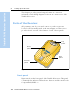
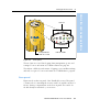
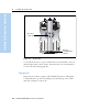
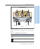
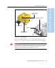
Table Of Contents
- Safety Information
- Introduction
- Trimble R7 GPS Receiver
- Overview
- Setting up the Receiver
- General Operation
- Configuration
- Transferring Data
- Software Utilities
- Specifications
- Default Settings
- Cables and Connectors
- Event Marker Input and 1PPS Output
- Trimble R8 GPS Receiver
- Overview
- Setting up the Receiver
- General Operation
- Configuration
- Software Utilities
- Specifications
- Default Settings
- Cables and Connectors
- Appendixes Trimble R7 / Trimble R8
- NMEA-0183 Output
- RTCM Output
- Troubleshooting
- Index

3 Setting up the Receiver
14 Trimble R7/R8 GPS Receiver User Guide
Trimble R7 GPS Receiver Operation
Figure 3.3 Rear panel
To mount the receiver on a pole, attach the receiver bracket to the pole
and then insert the catch lock into the bracket. For more information,
see Pole-Mounted Setup, page 22.
31.3 Top pan el
Figure 3.4 shows the top panel of the Trimble R7 receiver. This panel
contains the three power/serial data ports and (TNC) ports for GPS
and radio antenna connections.
compartment
Receiver
catch lock
Battery
catches