
User's Manual
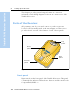
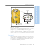
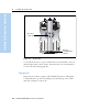
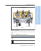
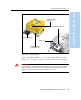
Table Of Contents
- Safety Information
- Introduction
- Trimble R7 GPS Receiver
- Overview
- Setting up the Receiver
- General Operation
- Configuration
- Transferring Data
- Software Utilities
- Specifications
- Default Settings
- Cables and Connectors
- Event Marker Input and 1PPS Output
- Trimble R8 GPS Receiver
- Overview
- Setting up the Receiver
- General Operation
- Configuration
- Software Utilities
- Specifications
- Default Settings
- Cables and Connectors
- Appendixes Trimble R7 / Trimble R8
- NMEA-0183 Output
- RTCM Output
- Troubleshooting
- Index

3 Setting up the Receiver
12 Trimble R7/R8 GPS Receiver User Guide
Trimble R7 GPS Receiver Operation
This chapter provides general setup information, connection
information, and cabling diagrams for the most common uses of the
Trimble R7 receiver.
3.1 Parts of the Receiver
All operating controls, ports, and connectors on the receiver are
located on its four main panels, as shown in Figure 3.1. This section
provides a brief overview of the features of each of these panels.
Figure 3.1 Panels on the Trimble R7 receiver
31.1 Front panel
Figure 3.2 shows the front panel of the Trimble R7 receiver. This panel
contains the five indicator LEDs, the two buttons, and the catch for the
CompactFlash/USB door.
Bottom
panel
Top
panel
Front
panel
Rear
panel