
User's Manual
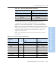

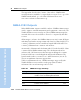
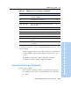
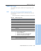
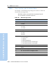
Table Of Contents
- Safety Information
- Introduction
- Trimble R7 GPS Receiver
- Overview
- Setting up the Receiver
- General Operation
- Configuration
- Transferring Data
- Software Utilities
- Specifications
- Default Settings
- Cables and Connectors
- Event Marker Input and 1PPS Output
- Trimble R8 GPS Receiver
- Overview
- Setting up the Receiver
- General Operation
- Configuration
- Software Utilities
- Specifications
- Default Settings
- Cables and Connectors
- Appendixes Trimble R7 / Trimble R8
- NMEA-0183 Output
- RTCM Output
- Troubleshooting
- Index

Trimble R7/R8 GPS Receiver User Guide 159
Cables and Connectors 19
Trimble R8 GPS Receiver Operation
This data cable may be used for firmware upgrades and other
computer functions with the Trimble R8 receiver. Power must be
supplied to the receiver through Port 1, or from the internal battery.
Note – Table 19.2 gives pinout information for the power/serial data cable,
(PN 32345) which is optional for use with the Trimble R8 receiver. This
cable can be used for firmware upgrades through Port 1, while also
supplying external power.
Note – Table 19.3 assumes that the cable is attached to the connector
labeled Port 1.
7 RTS5_232 8 CTS5_232
8 CTS5_232 7 RTS5_232
9 no connection RI5_232 9
Table 19.3 Power/serial data cable pinouts
Lemo 0-shell
connector
7 Pin
Direction DE9-F connector
7 Cond
Power lead
2 Cond
Pin Function Pin Color Function Color Function
1 GND
↔
5 Brown Signal ground
2 GND
→
Black V-OUT
3TX3_232
→
2 Orange TXD
4RTS/TXD
→
8Blue RTS
5CTS/RXD
←
7GreenCTS
6PWR_IN
←
Red Power IN (+)
7RX3_232
←
3YellowTXD
Table 19.2 Data-I/O cable pinouts (continued)
DB-9 Female
9 Pin
DB-9 Female
9 pin
Pin Function Pin Function