
User's Manual

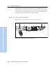
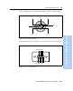
Table Of Contents
- Safety Information
- Introduction
- Trimble R7 GPS Receiver
- Overview
- Setting up the Receiver
- General Operation
- Configuration
- Transferring Data
- Software Utilities
- Specifications
- Default Settings
- Cables and Connectors
- Event Marker Input and 1PPS Output
- Trimble R8 GPS Receiver
- Overview
- Setting up the Receiver
- General Operation
- Configuration
- Software Utilities
- Specifications
- Default Settings
- Cables and Connectors
- Appendixes Trimble R7 / Trimble R8
- NMEA-0183 Output
- RTCM Output
- Troubleshooting
- Index

19 Cables and Connectors
156 Trimble R7/R8 GPS Receiver User Guide
Trimble R8 GPS Receiver Operation
This chapter provides pinout information for the Trimble R8 receiver
standard and optional cables. This information can be used to prepare
special cables for connecting the receiver to devices and instruments
not supported by the standard and optional cables.
19.1Port 1 and 2 Connectors
Figure 19.1 shows the location of the receiver serial ports.
Figure 19.1 Trimble R8 receiver serial ports
1
2
BARCODE S/N LABEL
Port 1
Port 2