
User's Manual

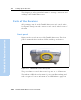
Table Of Contents
- Safety Information
- Introduction
- Trimble R7 GPS Receiver
- Overview
- Setting up the Receiver
- General Operation
- Configuration
- Transferring Data
- Software Utilities
- Specifications
- Default Settings
- Cables and Connectors
- Event Marker Input and 1PPS Output
- Trimble R8 GPS Receiver
- Overview
- Setting up the Receiver
- General Operation
- Configuration
- Software Utilities
- Specifications
- Default Settings
- Cables and Connectors
- Appendixes Trimble R7 / Trimble R8
- NMEA-0183 Output
- RTCM Output
- Troubleshooting
- Index

13 Setting up the Receiver
108 Trimble R7/R8 GPS Receiver User Guide
Trimble R8 GPS Receiver Operation
This chapter provides general information on setup, connection, and
cabling for the Trimble R8 receiver.
13.1Parts of the Receiver
All operating controls on the Trimble R8 receiver are located on the
front panel. Serial ports and connectors are located on the bottom of
the unit.
131.1 Front panel
Figure 13.1 shows a front view of the Trimble R8 receiver. The front
panel contains the three indicator LEDs, and the power button.
Figure 13.1 Trimble R8 receiver front panel
The power button controls the receiver’s power on or off functions.
The indicator LEDs show the status of power, satellite tracking, and
radio reception. For more information, see LED Behavior, page 119.