
User's Manual
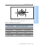
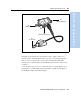

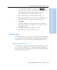
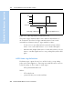
Table Of Contents
- Safety Information
- Introduction
- Trimble R7 GPS Receiver
- Overview
- Setting up the Receiver
- General Operation
- Configuration
- Transferring Data
- Software Utilities
- Specifications
- Default Settings
- Cables and Connectors
- Event Marker Input and 1PPS Output
- Trimble R8 GPS Receiver
- Overview
- Setting up the Receiver
- General Operation
- Configuration
- Software Utilities
- Specifications
- Default Settings
- Cables and Connectors
- Appendixes Trimble R7 / Trimble R8
- NMEA-0183 Output
- RTCM Output
- Troubleshooting
- Index

Trimble R7/R8 GPS Receiver User Guide 97
Event Marker Input and 1PPS Output 11
Trimble R7 GPS Receiver Operation
3. To start the GPS Configurator software, click , then
select Programs / Trimble / GPS Configurator / GPS Configurator.
The GPS Configurator dialog appears and the software
automatically connects to the Trimble R7 receiver.
4. In the General tab, select the Event marker check box.
5. Select the appropriate option, Positive slope or Negative slope,
depending on the type of pulse the external device uses.
6. Click
Apply.
The GPS Configurator software sends the new configuration
information to the receiver, and the receiver starts to accept
event marker input.
7. Click
OK to exit the GPS Configurator software.
The software disconnects from the receiver.
11.11PPS Output
The Trimble R7 receiver can output a one pulse per second (1PPS) time
strobe with an associated ASCII time tag output. The pulse is output
through Port 2 of the receiver using the event marker/1PPS cable.
111.1 1PPS pulse definition
The leading edge of the pulse coincides with the beginning of each UTC
second, as shown in Figure 11.1 on page 98. The pulse is driven by an
RS-422 driver between nominal levels of 0 V and 4 V. The leading edge is
positive, rising from 0 V to 4 V.