
User's Manual
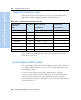
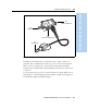
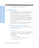
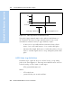
Table Of Contents
- Safety Information
- Introduction
- Trimble R7 GPS Receiver
- Overview
- Setting up the Receiver
- General Operation
- Configuration
- Transferring Data
- Software Utilities
- Specifications
- Default Settings
- Cables and Connectors
- Event Marker Input and 1PPS Output
- Trimble R8 GPS Receiver
- Overview
- Setting up the Receiver
- General Operation
- Configuration
- Software Utilities
- Specifications
- Default Settings
- Cables and Connectors
- Appendixes Trimble R7 / Trimble R8
- NMEA-0183 Output
- RTCM Output
- Troubleshooting
- Index

10 Cables and Connectors
92 Trimble R7/R8 GPS Receiver User Guide
Trimble R7 GPS Receiver Operation
Table 10.3 gives pinout information for the event marker/1PPS cable
which is supplied with the Trimble R7 receiver. The event marker/1PPS
cable is only used with the Trimble R7 receiver connectors labeled Port
1 ( for event marker output) and Port 2.
10.4GPS Antennas and Cables
The antenna that a receiver uses to collect satellite signals is
sometimes called a GPS antenna to distinguish it from a radio antenna.
Radio antennas are used for communication between receivers and
external networks or systems.
Note – Older models of antennas, such as Choke Ring or Micro-Centered
L1/L2, have different power requirements. The Trimble R7 receiver can
adjust the antenna power output when you designate the appropriate
antenna in the GPS Configurator software. For more information, see
Antennas, page 34.
Table 10.3 Event marker/1PPS cable pinouts
P1: Lemo 7-Pin
Port 2 Trimble R7
receiver
Direction P2: BNC-F
connector
(1PPS)
P3: BNC-F
connector
(Event
marker)
P4: Lemo 7s
Port 2 extension
Pin Trimble R7
receiver
function
Pin Pin Pin Function
1 Signal ground
←
1 Signal ground
2 GND
→
GND GND 2 GND
3 Serial data out
(TXD2)
←
3 Serial data in
(TXD2)
41PPS
←
Center pin 4 No Connect
5Event Marker
↔
Center pin 5 No Connect
6Power IN (+)
→
6Power IN (+)
7 Serial data in
(RXD2)
←
7 Serial data out
(RXD2)