
User's Manual
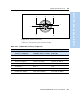
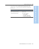

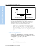
Table Of Contents
- Safety Information
- Introduction
- Trimble R7 GPS Receiver
- Overview
- Setting up the Receiver
- General Operation
- Configuration
- Transferring Data
- Software Utilities
- Specifications
- Default Settings
- Cables and Connectors
- Event Marker Input and 1PPS Output
- Trimble R8 GPS Receiver
- Overview
- Setting up the Receiver
- General Operation
- Configuration
- Software Utilities
- Specifications
- Default Settings
- Cables and Connectors
- Appendixes Trimble R7 / Trimble R8
- NMEA-0183 Output
- RTCM Output
- Troubleshooting
- Index

Trimble R7/R8 GPS Receiver User Guide 91
Cables and Connectors 10
Trimble R7 GPS Receiver Operation
Figure 10.3 Event marker/1PPS cable
In addition, the breakout box includes a Lemo 7-pin connector to
extend serial communications and/or power on Port 2. Because the
BNC connectors are used to service the event marker and 1PPS
features, pins 4 (1PPS) and 5 (Event Marker) are inactive on the Lemo
connector.
For Port 2 pinouts, see Port 1, 2, and 3 Connectors, page 88. For more
information on 1PPS input and event marker output, see Chapter 11,
Event Marker Input and 1PPS Output.
P4
P3
P1
P2
(Event marker)
(1PPS out)
(To Port 2)
(Port 2 extension)