ADL Vantage/ ADL Vantage Pro Users Guide
Notice PACIFIC CREST MAKES NO WARRANTY OF ANY KIND WITH REGARD TO THIS MATERIAL, INCLUDING, BUT NOT LIMITED TO, THE IMPLIED WARRANTIES OF MERCHANTABILITY AND FITNESS FOR A PARTICULAR PURPOSE. Pacific Crest shall not be liable for errors contained herein or for incidental consequential damages in connection with the furnishing, performance, or use of this material. This document contains proprietary information that is protected by copyright. All rights are reserved.
Contents Pacific Crest ADL Vantage/ADL Vantage Pro Users Guide ii
Introduction Welcome Thank you for purchasing the Advanced Data Link (ADL) Vantage or Vantage Pro. The ADL Vantage™ and ADL Vantage Pro radios are advanced, high speed, wireless data links that are designed specifically for GNSS/RTK applications but are also appropriate for many other applications requiring digital data links. Your success in using the ADL Vantage/ADL Vantage Pro is Pacific Crest’s primary goal. Pacific Crest stands behind its products by providing expert support and service.
User-selectable RF output ADL Vantage: Select between 0.1. 0.
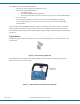
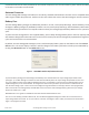
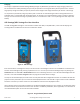
To configure the radio with ADLCONF software: • Connect the power supply to the wall/mains current • Connect the programming cable to: The power supply The ADL Vantage/ADL Vantage Pro radio Your PC (If your PC does not have a serial port, you may use a serial-to-USB adaptor) • Turn on the radio • Launch ADLCONF software and refer to the section of the ADLCONF User’s Guide on connecting the program to your radio. In most cases, you just need to click ADLCONF’s Con nect button.
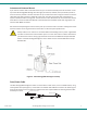
Antenna and Antenna Mount If you have an antenna with a male TNC connector, you can attach it directly to the RF connector on the top of the ADL Vantage/ADL Vantage Pro. We highly recommend, however, that you elevate your RF antenna as much as possible. The most common set up is similar to that seen in Figure 3 where an antenna cable with male TNC connector is attached to the radio. The other end of this cable is attached to a tripod or elevated section of range pole.
Each ADL data/power cable also connects the radio (and in some cases the data source) to external power via an SAEtype connector. Pacific Crest strongly recommends you use the ADL Vantage external battery (PN A01742) or the ADL Vantage Pro external battery (PN A00399), both of which include an SAE connector. These are sold both separately and as part of the battery/charger kits (ADL Vantage, PN K01107; ADL Vantage Pro, PN tbd).
provide the first level of shock protection for the internal components. An internal isolation system reduces the effect of vibration on the radio receiver board. Antenna Connector The ADL Vantage/ADL Vantage Prod radios use an industry standard TNC-female RF connector that is compatible with wide range of mobile whip antennas. Pacific Crest also sells cables that connect the ADL Vantage to remote antennas.
Charging The charger supplied with the ADL Vantage Battery/Charger kit (PN K01107) provides two-stage charging and should be connected to the battery following every full day of operation to assure good battery life and performance. The first stage quickly charges the battery to capacity and the second stage trickle charges the battery to maintain a full charge. It is important to periodically charge any battery that is stored for an extended length of time.
Function Description Parameter Choices Device Status Displays radio status and identification information Battery status Owner name Call sign Modulation type Channel bandwidth Transmitter status Firmware version Channel / Freq Displays/selects channel number & receive frequency Channel 01 and frequency (MHz) Channel 02 and frequency (MHz) Etc. Ch TX Freq Data Protocol Displays TX freq (if different from the channel’s RX freq) Displays/selects data protocol type Channel No.
Low intermediate power Intermediate power High intermediate power High power RX LED Meaning Displays/selects what it means when the RX LED flashes Signal Received Data Received Serial Baud Displays/selects serial baud rate of the radio’s data port 2400 4800 9600 19200 38400 115200 Signal Strength Displays strength of the received signal (RSSI) in dBm Advanced Menus Displays or Conceals rarely used functions Press Enter Hide Show CSMA Displays/selects Carrier Sense Multiple Access setting On O
The ADL Vantage and ADL Vantage Pro LCDs display radio parameters that are determined: • In the factory: serial number, firmware version, transmitter status (enabled/disabled) • By the radio: battery status, signal strength and error codes • By your dealer: channel tables (including frequency and bandwidth) and maximum transmit power • In the office using the ADLCONF program (everything else) In addition, you may configure the following parameters in the field using the ADL Vantage/Vantage Pro user interface:
protocol and the radio link rate. If you want to select a modulation type first and then an appropriate channel bandwidth, protocol and link rate, please use ADLCONF to configure the radio. Tips and Techniques for Best Performance Antenna Antenna placement is critical for good performance. Range and coverage is directly proportional to the height of the transmitting and receiving antennas in addition to antenna gain.
GPS RTK equipment is designed to function with intermittent gaps in the data. Heavy co-channel use may limit the ability of the ADL Vantage/ADL Vantage Pro radio to transmit the required information. In areas of heavy co-channel usage, try changing channels to a less used frequency. Security Code You can use the ADLCONF soft ware program to configure your ADL Vantage/ADL Vantage Pro to send and receive encrypted data.
matically be disabled (though the box will remain checked). However, if some of the radios in your system are non-Pacific Crest radios, you may need to turn Scrambling off. Forward Error Correction Forward Error Correction places extra bits in the transmitted data so receivers can check for transmission errors. Although data throughput is adversely affected, using Forward Error Correction can greatly improve range and so is strongly recommended.
• • Error Codes 15-16: If you are using the radio as a repeater, make sure that the transmit and receive frequencies are less than 10 MHz apart. Otherwise, you should return the radio for service. If the radio displays Error Code 15 (Transmit frequency lock error), it is important to stop using it because the crystal oscillator might be unstable and you might be transmitting at an unprogrammed frequency for which you are not licensed.
FCC Rules and Regulations Licensing Requirements It is the responsibility of the owner to comply with applicable rules and regulations concerning the operation of a radio transmitter. In the United States, the FCC regulates the licensing of this equipment. Application for a license is made by submitting FCC Form 600 along with evidence of frequency coordination (if required) and applicable fees. Similar licensing requirements exist worldwide.
The ADL Vantage/ADL Vantage Pro support the broadcast of station identification in a manner that meets the requirements of the FCC. Upon receipt of equipment, program your FCC call sign into the configuration of your ADL Vantage/ADL Vantage using ADLCONF software. This is only required for transmitters. ! Pacific Crest Warning: Failure to transmit your station identification is in violation of FCC regulations. Use ADLCONF software to enter your FCC call sign.
Contact Information Customer Support Quality, technology and service are the hallmarks of Pacific Crest. We provide easy access to our customer service department to keep you running efficiently. Headquarters EMEA Office Pacific Crest 510 DeGuigne Drive Sunnyvale, CA 94085 USA Tel: 1-800-795-1001 (U.S. & Canada toll free) 1-408-481-8070 (outside the U.S.
Warranty One-Year Limited Warranty This warranty gives you specific legal rights. You may also have other rights which vary from state to state or area to area. Pacific Crest warrants ADL family products, inclusive of cables and batteries, against defects in materials and workmanship for a period of one year from receipt by the end-user.
Appendix A - Safety Information Exposure to Radio Frequency Energy The ADL Vantage/ADL Vantage Pro is designed to comply with the following national and international standards and guidelines regarding exposure of human beings to radio frequency electromagnetic energy, in addition to protection against harmful interference of neighboring electrical equipment: • • • • • • • • • • • • • • FCC Report and Order FCC 96-326 (August, 1996) American National Standards Institute (C95.
Appendix B - Pin-outs and Connectors The ADL Vantage/ADL Vantage Pro uses a #1-shell, 5-pin circular data/power connector. For a mating connector, Pacific Crest recommends using a LEMO P/N FGG.1B.305.CLAD.72Z, or equivalent. Refer to Table 3 and Figure 8 for pin assignments and orientation. Figure 8 shows a rear view of the pin-outs (looking from behind the connector). Pin No.
Appendix C - Technical Specifications General Specifications Communication 1 RS-232 port, 115.2 kbps maximum User Interface 2-row, 16-character LCD display with 5 navigation buttons Power External ADL Vantage: 9.0 – 30.0 VDC, 2 Amp maximum ADL Vantage Pro: 9.0 – 30.0 VDC, 15 Amp maximum During RX 0.6 Watts nominal @ 12.0 VDC During TX ADL Vantage: 7 Watts nominal @ 12.0 VDC, 1 W RF output 13.4 Watts nominal @ 12.
Operating Temperature (Receiver) -40˚ to +85˚ C (-40˚ to +185˚ F) Operating Temperature (Transmitter) -40˚ to +65˚ C (-40˚ to +149˚ F) Storage Temperature (Receiver/Transmitter) -55˚ to +85˚ C (-67˚ to +185˚ F) Vibration Spec: MIL-STD-810F Mechanical Specifications ADL Vantage: 8.89 cm L x 4.6 cm W x 16.0 cm H (3.5” L x 1.809” W x 6.3” H) ADL Vantage Pro: 11.9 cm L x 8.6 cm W x 21.3 cm H (with handle) (4.7” L x 3.4” W x 8.37” H) ADL Vantage: 705 grams (1.55 lbs.) ADL Vantage Pro: 1950 grams (4.
510 DeGuigne Drive . . .