
User's Guide


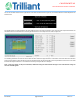


Table Of Contents
- 1 Overview
- 2 Features and Specifications
- 3 Functional Description
- 4 Antennas
- 5 Host PCB Requirements
- 6 SecureMesh Configuration
- 7 Regulatory Agency Approvals

DT-0237A page 23 of 34 Rev: 1.2
CONFIDENTIAL
DISTRIBUTED UNDER LICENSE
Figure 23 Coupon requirements to validate trace impedance
5.4.5 Other considerations
The only antennas, also describe is section 4.3, that can be used with the module using the reference trace design are the:
- Trilliant, CP-0299A, 4.8 dBi
- Linx, ANT-2.4-uSP, 3.8 dBi
- Larsen Antenna, RO2406NM, 6 dBi
- Mobile Mark, IMAG5-2400-3K-BLK-120, 5 dBi
- L-Com, HG2403RD-RTF, 3 dBi
- Mobile Mark, CVS-2400, 2.5 dBi
- Molex 1461530100, 3 dBi
The use of any other antenna or any changes to the reference trace design are subject to additional testing and authorization through a
Class II permissive change.
Modifying the RF Signal Routing
As previously mentioned, any changes to the RF traces is subject to approbation, additional testing and authorization through a Class II
permissive change on the FCC and ISED grants.
The objective is to use the W10 and W16 pads from OSDI module to route a micro-strip traces in order to obtain a uniform transmission
line with a characteristic impedance of 50 ohms. The characteristic impedance depends on the geometry of the trace and on the relative
dielectric constant of the PCB as shown in Figure 24. However, the characteristic impedance does not depend on the length of the trace.
Many tools are available on the web to help calculate the optimum dimensions.
Figure 24: Micro-strip trace parameters