Access Point Deployment Guide Models AP-R9-E and AP-R9-F System Release 2.1 Document Version 010-0021-00 Rev D Trilliant Holdings, Inc. 401 Harrison Oaks Blvd., Suite 300 Cary, North Carolina 27513 NOTICE The contents of this document are proprietary and confidential and the property of Trilliant Holdings, Inc., its subsidiaries, affiliates, and/or licensors. This document is provided subject to the confidentiality obligations set forth in the agreement between your company and Trilliant.
Proprietary Notice Copyright © Trilliant Holdings Inc. 2004 – 2019. All rights reserved. This document describes products, software and services (“Products”) of Trilliant Holdings Inc., its parents, subsidiaries, affiliates and/or its licensors. This document is licensed, not sold.
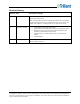
How to Contact Trilliant Use the following methods to contact Trilliant: General Company and Solution Information: http://www.trilliant.com/ Trilliant Headquarters: Tel: +1 919.495.6111 Solution and Customer Support Portal: https://support.trilliant.com/ Note: Make all requests for Solution support or RMA processing through the web portal. If you do not have a Support Portal login and password, or need your credentials reset, contact Trilliant Support using the email address below.
Revision History Revision Date Description of change B This version is Trilliant rebranded version of the document version A previously issued by Ingenu. April 26, 2017 Minor naming updates to replace On-Ramp with Trilliant, minor formatting and spelling changes Removed or replaced all instances of “On-Ramp” and “ORW” with “Trilliant” “On-Ramp Total View” replaced with “OTV”. C September 26, 2018 • • • • • D January 24, 2019 Updated footers and contact information.
Table of Contents Safety and Compliance ............................................................................................................................... 1 Safety Information .................................................................................................................................. 1 Compliance Notices ............................................................................................................................... 2 Modification Statement ..................
AP and Ancillary Equipment................................................................................................................ 23 AP Installation Configurations ............................................................................................................. 23 Base Station Configurations ................................................................................................................. 24 General Grounding Guidelines ....................................................
Site Survey Worksheet ............................................................................................................................. 63 AP Installation Configuration Worksheet .............................................................................................. 65 Basic AP Specifications............................................................................................................................. 69 Base Station Configuration ............................................
List of Figures Figure 1. Figure 2. Figure 3. Figure 4. Figure 5. Figure 6. Figure 7. Figure 8. Figure 9. Figure 10. Figure 11. Figure 12. Figure 13. Figure 14. Figure 15. Figure 16. Figure 17. Figure 18. Figure 19. Figure 20. Figure 21. Figure 22. Figure 23. Figure 24. Figure 25. Figure 26. Figure 27. Figure 28. Figure 29. Figure 30. Figure 31. Figure 32. Figure 33. Figure 34. Symbol for Used Electrical and Electronic Products ................................................................
List of Tables Table 1. Table 2. Table 3. Table 4. Table 5. Table 6. Table 7. Table 8. Table 9. Table 10. Table 11. Table 12. Table 13. Table 14. Table 15. Software Versions ..................................................................................................................... 7 Attenuation at 2.4 GHz for Common Types of Antenna Cables ............................................. 18 Surge Protector Mount Locations...............................................................................
Safety and Compliance Before installing the Access Point, read the instructions in this document. Safety Information The caution statements, warning conventions, and warning messages in this section apply to this product and manual. Trilliant strongly urges that you always follow all locally-approved safety procedures and safety instructions when working around high voltage lines and equipment.
WARNING: Hazardous voltage. Contact with hazardous voltage will cause death or severe personal injury. Follow all locally approved safety procedures when working around high- and low-voltage lines and equipment. WARNING: The Access Point is designed to be operated in accordance with normal safe operating procedures. These instructions are not intended to supersede or replace existing safety and operating procedures. Read all instructions before installing the Access Point.
Modification Statement Trilliant has not approved any changes or modifications to this device by the user. Any changes or modifications not expressly approved by Trilliant could void the user's authority to operate the equipment. Trilliant n’approuve aucune modification apportée à l’appareil par l’utilisateur, quelle qu’en soit la nature. Tous changements ou modifications qui ne sont pas approuvés par Trilliant peuvent annuler le droit d’utilisation de l’appareil par l’utilisateur.
Wireless Notice To satisfy FCC and Industry Canada Radio Frequency (RF) Exposure requirements for mobile and base station transmission devices, a separation distance of 20 cm or more should be maintained between the antenna of this device and persons during operation. To ensure compliance, operation at closer than this distance is not recommended.
European Union and European Free Trade Association (EU & EFTA) Compliance This equipment may be operated in the countries that comprise the member countries of the European Union and the European Free Trade Association.
Introduction This document provides network planning, installation, configuration and preventive maintenance information for the Access Point models AP-R9-E (ETSI standard) and AP-R9-F (FCC standard) as a part of the Total Reach Network (TRN). There are multiple configurations for the Access Point (AP) depending upon the country in which it will be used. Figure 2. Wireless Access Point (models AP-R9-E and AP-R9-F) This document is compatible with the software versions shown in the following table. Table 2.
Introduction Overview The AP is the core component of the Total Reach Network (TRN) and TRN base station solutions. It provides the functionality of an RF transceiver, a data processor, and a data router. The RF transceiver operates in the unlicensed 2.4 GHz ISM band on one of thirty-eight 1 MHz channels. The AP utilizes Time Division Duplexing and Direct Sequence Spread Spectrum with a proprietary Random Phase Multiple Access (RPMA) modulation technique.
Figure 3. High Level Diagram for Indoor Site Installation of AP and Equipment Figure 4. High Level Diagram for Outdoor Site Installation of AP and Equipment Note: The AP does not contain any user-serviceable components. Opening the AP voids the product warranty. Access Point Deployment Guide 9 NOTICE: The contents of this document are proprietary and confidential and the property of Trilliant Holdings, Inc., its subsidiaries, affiliates, and/or licensors.
Introduction For questions or technical assistance, contact Trilliant Customer Support (see How to Contact Trilliant on page iii). Referenced Documents The following document provides additional details about the AP. Provides detail about product specifications, characteristics, and requirements for the AP. • EMS Operator Guide 2.1 (010-0107-00) Provides instruction on using the Element Management System (EMS) to manage and monitor the Access Point.
Network Planning and Configuration Considerations Prior to the installation of an AP at a new location, a number of network design and configuration decisions must be addressed. This chapter provides an overview of these decisions which should be reflected in the AP Installation Configuration Worksheet provided in “Error! R eference source not found.” on page 69. Detailed network planning and configuration is outside the scope of this document.
Network Planning and Configuration Considerations • Assign AP channel (frequency) and Reuse Code • Determine antenna cable attenuation • Determine AP transmit power setting • The maximum permissible Effective Radiated Power, ERP, is determined by the regulations for the country where the AP will be installed (e.g., ETSI, FCC). The actual ERP is determined by the AP’s transmit power output, antenna gain and antenna cable loss.
• Transmit output power setting, most frequently automatically set by inserting antenna cable loss in dB when using the standard antenna for the country of operation. In the United States the standard antenna’s gain is 9 dBi. Backhaul Backhaul is the interconnection of the APs in a network to the back-office systems including the gateway and the element management system. The backhaul method to be used must be determined for each AP prior to installation.
Installation Prerequisites and Considerations Before starting the actual physical installation of an AP, it is very important to complete the prerequisite tasks outlined in this chapter as well as take into account the installation considerations indicated. Information gathering templates are provided in the appendices of this document. Installation Prerequisites Site Survey A site survey should be conducted prior to installation for all AP sites.
Installation Prerequisites and Considerations • Landlord contact information • AP power type, commercial power, solar solution or other • Specific landlord requirements • Distance to available power • Latitude • Longitude • Site type (building, tower, pole, or other) • Photos of site including antennal location, AP location, and the overall site • Height of existing structure • Other site-specific information • AP and equipment mounting locations AP Installation Configuration The AP installation
• Ethernet cable type and length, if required • Gateway port number • AP IP Address type, Static or Dynamic • Server port • AP IP Address assignment, if static • Reuse code • Netmask setting Installation Considerations When planning a new AP installation, the following items must be considered. AP Antenna The AP antenna should be mounted at a location that minimizes physical obstructions between the antenna and the endpoints with which it will be communicating.
Installation Prerequisites and Considerations The table below shows the attenuation for common types of antenna lines. Table 3. Attenuation at 2.4 GHz for Common Types of Antenna Cables Model Size dB/25 ft dB/50 ft dB/100 ft dB/150 ft dB/200 ft LMR-400 .40 inch 1.7 3.4 6.8 10.2 13.6 FSJ4-50B ½ inch 1.5 3.1 6.1 9.2 12.2 LDF4-50A ½ inch .9 1.9 3.7 5.6 7.4 AVA5-50 ⅞ inch .5 1.0 1.9 2.9 3.8 AVA7-50 1⅝ inch .3 .6 1.2 1.8 2.
Figure 5. PCTEL GPS Model GPSL1-TMG-SPI-40NCB The PCTEL GPSL1-TMG-SPI-40NCB GPS antenna has a type-N female connector. Note: Most GPS antennas have a Low Noise Amplifier (LNA) that requires power from the AP. The AP supplies 3.3 V at up to 50 ma. If this current is exceeded, the AP detects the excess current and shuts down its GPS power supply. When this occurs, the AP sends a GPS antenna fault message back to the EMS. The AP must be power cycled to restore power to the GPS antenna.
Installation Prerequisites and Considerations AP DC Power Requirement The AP is powered over the Ethernet port using a PoE injector. The acceptable power source voltage range is 38 – 72 VDC. At the nominal input voltage of 48 VDC the typical input current is 0.3 Amps. The maximum input power dissipation is 17 Watts. When connecting to the distribution panel of a 48 VDC power system, it should be fused with a minimum of a ½ Amp slow-blow fuse. The maximum fuse or circuit breaker size should be 2 Amps.
Cable Type Manufacturer Part Number RJ45 Connector Type Manufacturer Part Number CAT 5E UTP Solid, 24 AWG Cable DC-5E8-RD-1K-L Pan Pacific CAT 5E UTP RJ45 Connectors, for Solid Cable CN150-45-1 www.wallcoinc.com CAT 5E, STP Solid, 24AWG Cable 10X6-521TH CAT 5E, STP Stranded, 24AWG Cable 10X6-521SH www.CableWholesale.com www.CableWholesale.com Mfg: Abergetty Supplied by: www.deepsurplus.
Installation Prerequisites and Considerations Solar Power Solar Power is recommended for sites where commercial power is not available or is not cost effective to install. The required size for the solar panel and battery system is strongly influenced by the geographic area in which it will be used. We offer a solar powered base station solution that may be appropriate for your application. Contact Trilliant Customer Support for more information (see “How to Contact Trilliant” on page iii).
AP Installation AP and Ancillary Equipment The AP installation includes installing the AP itself and the ancillary equipment listed below: • Access Point (AP) • AP antenna • AP antenna cable (50 ohm coaxial cable) • AP antenna cable lightning suppressor • GPS antenna • GPS antenna cable (50 ohm coaxial cable) • PoE injector, powered by 48 VDC • Site-specific power solution providing 48 VDC to the PoE, if not using the 120/240 VAC powered base station cabinet or the solar powered base station
AP Installation page 69. The AP is designed to be installed indoors or outdoors. It may be mounted in any position indoors but should be mounted with its connectors facing down when installed outdoors. The AP may be installed in an equipment cabinet with its ancillary equipment if desired.
Figure 7. High Level Grounding Diagram Grounding the AP and Antenna Cable Surge Suppressor A ground wire may be attached underneath one of the AP mounting bolts. A ground wire must be attached to the ground terminal on the inline coaxial surge protector which is inserted between the AP’s type N female antenna connector and the AP antenna cable. An example is shown in the following figure.
AP Installation Figure 8. Grounding the AP Access Point Deployment Guide 26 NOTICE: The contents of this document are proprietary and confidential and the property of Trilliant Holdings, Inc., its subsidiaries, affiliates, and/or licensors. This document is provided subject to the confidentiality obligations set forth in the agreement between your company and Trilliant. The contents may not be used or disclosed without the express written consent of Trilliant.
Grounding the AP and GPS Antennas If the AP and GPS antennas are not attached to grounded metal structures a ground wire should be attached to the base of both antennas. An example of grounding these two antennas is shown in the following figure. Figure 9. Grounding the GPS and AP Antennas Access Point Deployment Guide 27 NOTICE: The contents of this document are proprietary and confidential and the property of Trilliant Holdings, Inc., its subsidiaries, affiliates, and/or licensors.
AP Installation AP Mounting Details Mounting options for the AP are discussed in this section. The AP is supplied with four mounting tabs that facilitate attaching the AP to a wall, in a cabinet, or to a strut channel, if required. The mounting tabs are attached to the AP by the installer using four provided, 5/16inch self-tapping, hex head bolts. See the mounting tabs shown in Figure 10. Figure 10. AP with Mounting Tabs Installed AP Pipe Mount Option We offer an optional pipe mount kit for the AP.
Hardware Installation Verification Power Verification Prior to applying power to the AP, confirm with a Digital Voltmeter (DVM) that the DC voltage is correct at the PoE injector. The DC voltage should be between 48 VDC and 54 VDC. Note: The AP its self is not polarity sensitive, however, it is recommended that the barrel of the PoE power plug be at ground potential if the power system is grounded.
Hardware Installation Verification If the Return Loss is not acceptable, the antenna should be disconnected and the antenna line should be terminated with a 50 ohm load. The Return Loss test should be repeated. If the antenna line Return Loss is now greater than 20 dB and is flat across the frequency range, the antenna should be replaced.
o Type and length of coaxial cable should be recorded for each run. Grounding Verify that the mounting hardware, AP, antenna cable, and lightning suppressor are properly grounded. Connector Weather Sealing Verify that all outdoor connectors are properly weather sealed. Mounting Hardware Verify that all mounting hardware is tight and secure. Access Point Deployment Guide 31 NOTICE: The contents of this document are proprietary and confidential and the property of Trilliant Holdings, Inc.
AP Software Configuration via Web Interface The AP web interface can be accessed with a web browser connected locally at the data port of the PoE injector or remotely through the backhaul network. We recommend that you use one of the following internet browsers when using the AP web interface: • Microsoft Internet Explorer® 8 or higher • Mozilla Firefox®, any version • Google Chrome™, any version Note: The AP web interface described in this chapter is compatible with AP software version 6.6.
AP Software Configuration via Web Interface immediately following the physical AP installation. In most cases, it is strongly recommended that the initial configuration be performed prior to installation. Refer to Figure 6 on page 20 for the connections required to configure an AP. If the AP is being installed with a 3G wireless modem for backhaul, refer to “Initial AP Network Configuration for 3G Wireless Backhaul Modem” on page 34.
1. To access the AP configuration page, ensure the following: o You are on the same subnet with the AP or your router can route to the AP IP address. The AP’s default router setting is 192.168.1.254. o You have access to port 443 on the firewall 2. Open your web browser. 3. In the address bar of the browser, type https://192.168.1.1. A dialog box opens that looks similar to the following: Figure 13. Username and Password Prompt 4. Enter the default User Name and Password.
AP Software Configuration via Web Interface Figure 14. Access Point Configuration Interface Home Page Block A above shows the four menus (i.e., Home, Access Point, Statistics, and Admin) that can be used to navigate to different configuration pages. Block B shows four buttons that allow you to do the following: o Enable/Disable RF If the RF is disabled, the AP is still connected to the Gateway.
Figure 15. AP Status page Home Page On the Home Page, there are two submenus—Dashboard and About. Figure 16. Home Page Dashboard Submenu Figure 17. Dashboard submenu The Dashboard is the initial screen that is displayed after logging in (shown below). The Dashboard displays GPS signal information. Access Point Deployment Guide 37 NOTICE: The contents of this document are proprietary and confidential and the property of Trilliant Holdings, Inc., its subsidiaries, affiliates, and/or licensors.
AP Software Configuration via Web Interface Figure 18. GPS Signal Information If the AP has GPS connected to it, GPS values are shown. Note: GPS verification MUST occur after completion of physical AP installation. The columns on this screen are defined in the following table. The rows show the number of GPS satellites to which the AP receiver is currently locked. For proper GPS synchronization, there should be a minimum of five satellites. Table 6.
About Submenu Figure 19. About submenu The About screen displays device specifications for the AP such as manufacturer, device type, MAC address of the AP, hardware, firmware, and software versions. There is nothing to configure on this screen, therefore the fields cannot be edited. Figure 20. Device Specification Access Point Menu Figure 21.
AP Software Configuration via Web Interface TRN Config Submenu The Total Reach Network (TRN) Configuration screen (shown below) displays network configuration parameters at the time the AP was deployed. Figure 22. Network Configuration screen The following table defines the fields on this screen. To edit these fields, click on the Disable RF button. After you make the changes, click on the Save button and then the Enable RF button. Note: If you disable the RF, the AP is still connected to the Gateway.
Field Unit Description Reuse Code Decimal Different Reuse Codes allow two APs to operate on the same Channel and System ID without interference. Range is 0 – 255. Center Frequency MHz This field is not editable. The value for center frequency is determined from the setting for the Channel field. Broadcast Gold Code Hex This field is not editable.
AP Software Configuration via Web Interface Figure 23. Field Configuration screen Access Point Deployment Guide 42 NOTICE: The contents of this document are proprietary and confidential and the property of Trilliant Holdings, Inc., its subsidiaries, affiliates, and/or licensors. This document is provided subject to the confidentiality obligations set forth in the agreement between your company and Trilliant. The contents may not be used or disclosed without the express written consent of Trilliant.
The following table defines the fields on this screen. To edit these fields, click on the Disable RF button. After you make the changes, click on the Save button and then the Enable RF button. Note: If you disable the RF, the AP is still connected to the Gateway. Note: The maximum transmit power for the AP and the Node is based on the setting in the Regulatory Domain field. Table 8.
AP Software Configuration via Web Interface Field Unit/Format Description Node Cable Loss dB Default setting is 0 dB. Contact Trilliant Customer Support prior to changing this parameter. Node Antenna Gain dBi Default setting is 2 dBi. Contact Trilliant Customer Support prior to changing this parameter. Node Maximum Transmit Power dBm This field is not editable. The value is determined by the settings for Regulatory Domain and the other Node Transmit Parameters.
Figure 24. Backhaul Configuration screen The following table defines the fields on this screen. To edit these fields, click on the Disable RF button. After you make the changes, click on the Save button and then the Enable RF button. Note: If you disable the RF, the AP is still connected to the Gateway. Table 9.
AP Software Configuration via Web Interface Field Unit Description Total Reach Gateway Hostname/IP Address N/A • For Server mode, this field is grayed out and not accessible. Total Reach Gateway Port Number N/A Enable HTTP Tunneling? N/A • For Client mode, the Total Reach Gateway IP Address or Fully Qualified Domain Name (FQDN) should be entered here. • For Server mode, this field is grayed out and not accessible. • For Client mode, this field should be set to 5051.
Figure 25. Site Survey screen Statistics Menu Figure 26. Statistics menu The Statistics menu has the following submenus: • Throughput • Counters Throughput Submenu The Throughput screen (shown below) provides a graph of uplink throughput in bits per second. Access Point Deployment Guide 47 NOTICE: The contents of this document are proprietary and confidential and the property of Trilliant Holdings, Inc., its subsidiaries, affiliates, and/or licensors.
AP Software Configuration via Web Interface Figure 27. Throughput screen Counters Submenu The AP Counters screen (shown below) provides various counters for uplink and downlink. Figure 28. AP Counters screen Admin Menu Figure 29. Admin menu Access Point Deployment Guide 48 NOTICE: The contents of this document are proprietary and confidential and the property of Trilliant Holdings, Inc., its subsidiaries, affiliates, and/or licensors.
The Admin menu has the following submenus: • Security • Network • Logs Security Submenu The following Security Configuration screen provides information related to system services, administrator password, and SNMP configuration. Access Point Deployment Guide 49 NOTICE: The contents of this document are proprietary and confidential and the property of Trilliant Holdings, Inc., its subsidiaries, affiliates, and/or licensors.
AP Software Configuration via Web Interface Figure 30. Security Configuration screen The following table defines the fields on this screen. Access Point Deployment Guide 50 NOTICE: The contents of this document are proprietary and confidential and the property of Trilliant Holdings, Inc., its subsidiaries, affiliates, and/or licensors. This document is provided subject to the confidentiality obligations set forth in the agreement between your company and Trilliant.
Table 10. Parameters on the Security Configuration Screen Field Description System Services Preferences Options are: • Disable Tenet login? • Enable SSL for Sockets? Change ‘admin’ Password Old Password To change the password, you must first enter the old password. New Password Enter the new password. Re-type to Confirm Re-type the new password to confirm the change.
AP Software Configuration via Web Interface Field Description Write Community Specifies SNMPv2c community string (password) for read-write access to the full tree of SNMP managed objects. The default value is Private. Minimum Security Level Specifies SNMPv3 minimum security level. From the dropdown menu, the options are: • No Auth No Priv: Allows unauthenticated requests. • Auth No Priv: Allows authenticated requests without privacy or encryption.
Network Submenu The Network Configuration screen (shown below) allows you to change the AP IP address, netmask, and default router as well as other network configuration parameters such as Ethernet speed and MTU, duplex mode, and DNS and NTP servers. Figure 31. Network Configuration screen The following table defines the fields on this screen. Table 11.
AP Software Configuration via Web Interface Field Description • If the primary interface settings are modified, the current values roll over to secondary and the secondary interface is enabled on reboot. • If the AP is rebooted with incorrect primary interface settings, it can still be accessed using the old settings via the secondary interface.
Field Description NTP Servers The AP should be configured with valid NTP servers for correct time synchronization. If the AP is not configured, it may have problems connecting to the Total Reach Gateway using SSL. The following NTP server addresses are the defaults: • nist1-nj.ustiming.org • nist1-atl.ustiming.org • nist1-la.ustiming.org • nist1-sj.ustiming.org • nist1-lv.ustiming.org • time.nist.
AP Software Configuration via Web Interface • Error: This setting shows error and critical log information. • Warning: This setting shows warning, error, and critical log information. • Informational: This setting shows informational, warning, error, and critical log information. • Debug: This setting shows debug, informational, warning, error, and critical log information. Figure 32. Logs screen Only the last 100 log entries are shown on this screen.
AP Communication Troubleshooting Before you leave the installation site, contact your network operations center (NOC) to verify that the AP is online and successfully communicating. If remote communication with the AP is not possible, perform the following steps: 1. Manually configure the following on a laptop: o The IP address of the Ethernet port o Netmask setting o The Default Router setting 2. Unplug the backhaul connector from the data port of the PoE and connect the laptop to that port. 3.
AP Communication Troubleshooting Figure 34. Sample Method for On-Site Debugging of an Application Access Point Deployment Guide 58 NOTICE: The contents of this document are proprietary and confidential and the property of Trilliant Holdings, Inc., its subsidiaries, affiliates, and/or licensors. This document is provided subject to the confidentiality obligations set forth in the agreement between your company and Trilliant.
Troubleshooting Guidelines Use the following table to help troubleshoot a problem. Table 12. Troubleshooting Guide Problem Action AP does not power up (Status LED is not illuminated or flashing) • When the AP is powered, the Status LED illuminates or flashes. If not, check the Ethernet cable and connector for damage. • Verify that the PoE injector is connected properly (i.e., the AP is connected to Data + Power side).
Troubleshooting Guidelines Problem Action AP does not acquire GPS • Verify that the GPS antenna cable and the AP antenna cable are connected and have not been swapped. If the connectors were swapped, it is necessary to power cycle the AP. • Disconnect both ends of the GPS. Verify continuity and that the cable is not shorted. • Verify the GPS antenna is not defective by substituting a known working GPS antenna.
Preventive Maintenance The recommended preventive maintenance schedule for the AP is shown in the following table. For additional assistance, contact Trilliant Customer Support (see “How to Contact Trilliant” on page iii). Note: Do NOT open the AP enclosure. Doing so voids the product warranty. Table 13. Preventive Maintenance Schedule Task Frequency 1. Verify that all connections are tight and secure. Annually 2. Verify that there is no visible damage to any wires or cables. Annually 3.
A Site Survey Worksheet Site Survey Required Information Completed Site name AP ID Site street address or other location information Site access information Landlord contact information Specific landlord requirements (Attach another sheet if there is significant information) Latitude Longitude Site type (building, tower, pole, or other) Height of existing structure AP equipment mounting location AP antenna mounting location and height Access Point Deployment Guide 63 NOTICE: The contents of this docum
Site Survey Worksheet Site Survey Required Information Completed Antenna line length required GPS mounting location GPS line length AP power type, commercial power, or solar solution Distance to commercial power, if available Photos of site including antennal location, AP location, and overall site (Attach all photos to this worksheet.) See attachments.
B AP Installation Configuration Worksheet AP Installation Configuration Required information Completed Site name AP Name AP ID Deployment Region ID AP physical configuration (Outdoor, indoor, standalone, in cabinet, or other) Power source (120/240 VAC, 48 VDC, or solar) AP antenna manufacturer AP antenna model AP antenna gain AP antenna downtilt AP antenna cable type Access Point Deployment Guide 65 NOTICE: The contents of this document are proprietary and confidential and the property of Trilliant Ho
AP Installation Configuration Worksheet AP Installation Configuration Required information Completed AP antenna cable length AP antenna cable loss GPS antenna model GPS cable type GPS cable length Backhaul type Backhaul equipment location Backhaul configuration information Power over Ethernet (PoE) injector location Ethernet cable type Ethernet cable length AP Static or DHCP IP address (Static or Dynamic?) AP IP address (Default: 192.168.1.1) Netmask setting (Default: 255.255.255.
AP Installation Configuration Required information Completed Channel assignment Reuse Code Access Point Deployment Guide 67 NOTICE: The contents of this document are proprietary and confidential and the property of Trilliant Holdings, Inc., its subsidiaries, affiliates, and/or licensors. This document is provided subject to the confidentiality obligations set forth in the agreement between your company and Trilliant.
C Basic AP Specifications The AP is equivalent to a base station. The following table provides the basic AP specification information. Table 14. Basic AP Specifications Size Inches: 9.1”H x 8.1”W x 4.5”D Millimeters: 232mm H x 202mm W x 111mm D Maximum Weight Pounds: 9.6 Kilograms: 4.35 Operating Environment Outdoors or indoors Enclosure IP66 Operating Temperature Range -40°C to +80°C Power Source Voltage Range (PoE) 38 – 72 VDC, Nominal 48 VDC Power over Ethernet Current Consumption 0.
D Base Station Configuration Table 15. TRN Base Station Configuration Options Base Station Option Description TRN-1011 Base Station • Outdoor base station • 120/240 VAC powered system with 8 hours of battery backup • AP is located in the equipment cabinet along with a 3G modem and battery backup Applications Required Hardware Additional Items Required Outdoor locations with AC power requiring 3G modem backhaul.
Base Station Configuration Base Station Option Description TRN-1021 Base Station Applications Required Hardware Additional Items Required • Access Point • Solar powered Outdoor locations without power requiring 3G modem backhaul.
Base Station Option Description TRN-1032 Base Station • Rack-mounted base station • Contains a 19-inch rack 3RU shelf • Powered by either 120/240 VAC or 48 VDC • AP is mounted outdoors Applications Required Hardware Additional Items Required Secure locations with indoor rack mount environment, power and access to corporate IP network.
E Abbreviations and Terms Table 16. Abbreviations and Terms Abbreviation/Term Definition AP Access Point. The component geographically deployed over a territory. (Models APR9-E and AP-R9-F ) CIMA Critical Infrastructure Monitoring Application. The network component that passes data from the Gateway to the associated upstream databases. This product name is now OTV.
Abbreviations and Terms Abbreviation/Term Definition GW Gateway IC Industry Canada IETF Internet Engineering Task Force IP Internet Protocol IPsec Internet Protocol Security NID Node ID NIST National Institute of Standards and Technology Node The wireless module that integrates with OEM sensors and communicates sensor data to an Access Point. Also, the generic term used interchangeably with eNode or microNode.