
Gas Cooker User Manual


34
Connecting to gas supply
This appliance is designed to be installed
with an appliance flexible connection only.
Supply piping should not be less than R
3
/8.
Connection is made to the Rc ½ (½” B.S.P.)
female threaded entry pipe located just
below the hotplate level on the rear left hand
side of the appliance. NOTE: ONLY LIQUID
SEALANTS TO BE USED WHEN INLET
GAS PIPE IS FITTED I.E.: DO NOT USE
P.T.F.E. SEALANT TAPE.
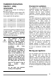
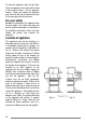
Carry out a gas tightness test after
connecting to the gas supply. The gas
bayonet connector must be fitted in the
shaded area indicated in Fig.2. Take into
account that it must be possible to pull the
appliance forward sufficiently. Ensure the
hose does not become trapped when
pushing the appliance into position.
IMPORTANT: FLEXIBLE TUBING USED
MUST COMPLY WITH BS.669 CURRENT
EDITION.
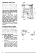
Fitting the stability bracket
It is recommended that if the appliance is to
be installed with a flexible supply pipe, a
stability bracket be fitted and is available
from your supplier (see Important Safety
Requirements). These instructions should
be read in conjunction with any leaflet
packed with the stability bracket.
1. Place the appliance in its intended
position and level appliance.
2. Mark off 300mm from the left hand side
of the appliance as shown in dimension
'A', Fig 3a. This is the centre line of the
fixing bracket.
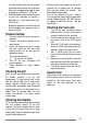
3. Draw a line 100mm from the front edge
of the feet (see Fig.3a) and remove
appliance from its position. Mark off
dimension 'B' (see Fig.3a) back from this
line on the centre line of the bracket to
locate the front edge of the lower
bracket.
487mm (B)
300mm
100mm
20mm
(A)
(C)
Fig.3a.
Fig.3b.
250
850
450
700
400
50
100
Fig.2.