
User manual


5
INSTALLATION
IMPORTANT
It is essential that a competent installer is
employed to fit this appliance.
The manufacturer will not accept liability, should
the above instruction or any of the other safety
instructions incorporated in this book be ignored.
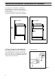
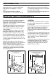
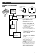
On the end of the shaft, which includes the GJ
1/2" threaded nut, adjustment is fixed so that the
washer is interposed between the components
as shown in Figure 1. Screw the parts together
without using excessive force, orientate the
adjustment in the desired direction and then lock
it all together.
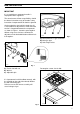
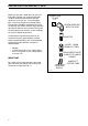
A) Multi positional 'L' type connector
B) Main gas pipe
C) Hob fixing bracket
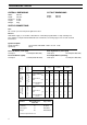
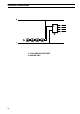
Rectangular cut-out size for hob
Fig. 2
Fig. 1
A) End of shaft with nut
B) Washer
C) Adjustable join
It is important to install the elbow correctly, with
the shoulder on the end of the thread, fitted to
the hob connecting pipe.
Failure to ensure the correct assembly will
cause leakage of gas.
Fig. 3
ABC
FO 0264
FO 0814
FO 0508
FO 2065
480
560
510
580