
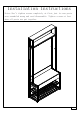
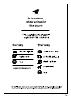
Use and Care Manual
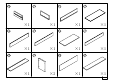

M6×28mm
∅3.5×35mm
∅6×12mm
4
4
21
A
B
C
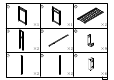
PART NO. QTY.
PARTS
PART NO. QTY.
PARTS
∅6×30mm
24D
∅6×35mm
14E
∅7×38mm
2F
1G
M6
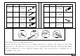
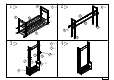
step 1
step 2
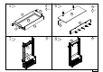
step 4
step 3
Installation of Cams and Pains:
Screw the Pin into hole.To set Cams correctly ,ensure the arrow on the Cam
opening to the holes of the pin it is locking.Lock Cam by turning Cam head
with screwdriver to be tighten.Please don't use an electric screwdriver to
assemble the unit.
P.8-4
2H
M4*20mm