
Manual


27
$%! 'F$*$%""
@7?4;704>?=4-@?4:9,941:7/>
The maximum number of boilers that can be piped in
series is five. If installing more than five boilers you will
need to install the boilers in banks of no more than 5 boil-
ers per bank. The multiple banks should only consist of
Primary Secondary Cascade Kits to ensure adequate flow
through boilers. The system piping between these boiler
banks should be piped in parallel, see Figure 29, page 31.
The parallel system piping between banks may require a
balancing valve(s) if installing an uneven number of boil-
ers per bank (i.e. 4 boiler bank, with a 2 boiler bank), see
Figure 30, page 32.
$D>?08"4;492
%30 >D>?08 ;4;492 8@>? -0 , G.7:>0/H >D>?08 ?:
,A:4/,9D:CD209.:9?,849,?4:9,9/;:?09?4,71,47
@=0:1?30,>.,/0
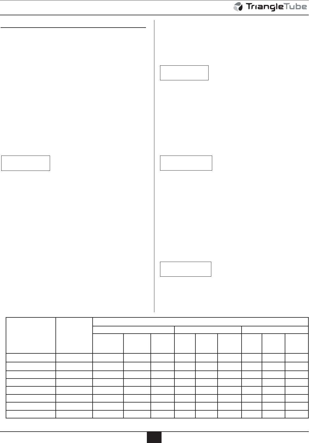
1. The minimum recommended system iron pipe size is
listed in Table 9. This table provides the individual
boiler and system flow rates at various system tem-
perature differences. This table also lists system pip-
ing pressure drops per 100 feet of system piping.
2. To determine the system pressure drop, calculate
the total equivalent length (T.E.L.) of pipe for each
valve and fitting in the system piping in the appro-
priate pipe size using Table 10 page 28. Add the
T.E.L. to the actual straight length of system pipe
of the same size.
3. Once you have calculated the T.E.L. of system pipe
based on a specific pipe size, multiply it by the pressure
NOTICE
drop/100 feet listed for the pipe size to establish the total
c
ircuit pressure drop for that pipe size. If using various
pipe sizes in the system, you will need to do this calcula-
tion for each pipe size separately and add the total pres-
sure drops of all sizes to get a total system pressure drop.
(309 >4E492 ?30 >D>?08 ;4;492 ,9/ .:8;:909?> 4?I>
=0.:8809/0/?:@>0,84948@817:B=,?0:12;8
;0=$:7:-:470=:=2;8;0=$:7:-:470=49?30
.,>.,/0?:7484??3017:BA07:.4?D?:100?>0.:9/,9/
?301=4.?4:97:>>;=0>>@=0/=:;?: 100?100?:1
;4;0 $4E0 >D>?08 ;4;492 ,9/ .:8;:909?> @>492
,;;=:A0/=0.:294E0//0>42980?3:/>4190.0>>,=D.:9
?,.?%=4,9270%@-0%0.394.,7$@;;:=?1:=,>>4>?,9.0
? 4> =0.:8809/0/ ?: @?474E0 , ;=48,=D>0.:9/,=D
,>.,/0 B309 ?30 ?:?,7 >D>?08 17:B =,?0 4> 2=0,?0=
?3,92;8;0=$:7:-:470=:=2;8;0=$:7:
-:470=:=70>>?3,92;8;0=$:7:-:470=:=
2;8 ;0= $:7: -:470= ;=48,=D>0.:9/,=D
,>.,/04>,7>:=0.:8809/0/B309?30>D>?0817:B
=,?0,9/;=0>>@=0/=:;,=0@969:B9
See Figure 31, page 33 for P/S Cascade system piping.
See Figure 32, page 34 for R/R Cascade system piping.
%: ,A:4/ ;:?09?4,7 .:9?,849,?4:9 :1 ?30 -:470= ;4;492
,9/ 30,? 0C.3,920=> 9>?,77 :;?4:9,7 >?=,490= 64?
"$$:9?30>D>?08=0?@=9;4;492?:-:470=>49,9D
##,>.,/0,;;74.,?4:9B4?3:=B4?3:@?-:470=A,7A0>
NOTICE
BEST PRACTICE
NOTICE
CSD-1 Piping & Control Installation
%,-704948@8#0.:8809/0/$D>?08=:9"4;0$4E0,9/"=0>>@=0=:;00?:1"4;0
Individual Boiler
or Cascade Kit
P/N
Total Output
MBH
System Temperature Difference (F)
20 30 40
GPM
Iron Pipe
Size
∆P/100
Feet GPM
Iron
Pipe
∆P/100
Feet GPM
Iron
Pipe
∆P/100
Feet
Solo 250 223 22 1.5” 3.4 15 1.25” 3.5 11 1.25” 2.0
Solo 399 379 38 2” 2.8 25 1.5” 4.2 19 1.5” 2.6
C(PS or RR)500 446 45 2” 3.5 30 2” 1.8 22 1.5” 3.4
C(PS or RR)800 758 76 3” 1.4 51 2.5” 1.9 38 2” 2.8
C(PS or RR)1000 892 89 3” 1.9 59 2.5” 2.5 45 2” 3.5
C(PS or RR)1200 1,138 114 4” 0.8 76 3” 1.4 57 2.5” 2.5
C(PS or RR)1600 1,518 152 4” 1.4 101 3” 2.5 76 3” 1.4
C(PS or RR)2000 1,897 190 4” 2.1 126 4” 1.0 95 3” 2.2