
Manual


Installation
23
D/=:94.@9.?4:9
The hydronic junction serves as a low loss header provid-
ing hydraulic separation, dirt separation and air elimination.
(309@?474E492,3D/=:94.5@9.?4:9?3084C0/>D>?08
>@;;7D?08;0=,?@=0.,9-0.,7.@7,?0/,>1:77:B>
(309?30-:470=,>.,/017:B=,?0/:0>9:?0<@,7?30
>D>?08 17:B =,?0 ?30 ?:?,7 30,? :@?;@? :1 ?30 -:47
0=>,>.,/0B477-0,->:=-0/-D?30>D>?08B309?30
1:77:B492.:9/4?4:9>,=080?
%30 -:470=,>.,/0 >@;;7D ?08;0=,?@=0 4>
2=0,?0=?3,9?30>D>?08>@;;7D?08;0=,?@=0
%30-:470=,>.,/017:B=,?04>70>>?3,9?30
>D>?0817:B=,?0
%30=0?@=9?08;0=,?@=0:1?30>D>?084>0<@,7
?: ?30 =0?@=9 ?08;0=,?@=0 :1 ?30 -:470=
,>.,/0
%3049>?,77,?4:9:1?303D/=:94.5@9.?4:9:97D,;;740>
B309?30,>.,/0>D>?084>.:9142@=0/49,;=48,=D
>0.:9/,=D ,==,920809? %30 8,C48@89@8-0=:1
-:470=>?3,?.,9-0;4;0/@;?:,>492703D/=:94.5@9.
?4:94>14A0%303D/=:94.5@9.?4:9.,9-049>?,770/:9
04?30=?30=423?:=701?>4/0:1?30/4>?=4-@?4:98,94
1:7/ %30 3D/=:94. 5@9.?4:9 .,9 -0 =:?,?0/
/02=00>,-:@?4?>30423?:=A0=?4.,7,C4>
1. Place the hydronic junction in the location to be
installed. The distribution manifold must be consid-
ered in determining location.
2. Connect the hydronic junction to the distribution
manifold using the gaskets and hardware provided.
3. Level distribution manifold and hydronic junction.
NOTICE
NOTICE
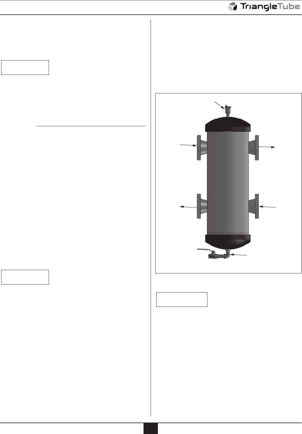
4. Install air vent and drain valve in the Hydronic
J
unction, see Figure 23. The air vent should be
installed in the top tappings as shown. The drain
valve (1-1/4” NPT shut off valve) should be
installed horizontally using a 1- 1/4” NPT 90º elbow
and 1-1/4” NPT x 4” nipple in the tapping located at
the bottom. The handle on the shut off valve will
need to be in the horizontal position when the valve
is closed. Remove handle and install accordingly.
I9>@7,?4:9
?I> =0.:8809/0/ ?: 49>?,77 49>@7,?4:9 ?: 849484E0
>?,9/-D7:>>0>
Position and secure insulation to hydronic junction as
shown in Fig. 23.
BEST PRACTICE
Air
Vent
Boiler
Supply
Boiler
Return
System
Supply
System
Return
Drain
Valve
42D/=:94.@9.?4:9
System
Supply Temp.=
[(Boiler Supply Temp. x Boiler Flow Rate) +
(System Return Temp. x Bypass Flow Rate)]
System Flow Rate
Bypass
Flow Rate
(System Flow Rate - Boiler Flow Rate)
=