
Install Instructions
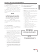


Table Of Contents

4
CHAPTER 2
CHAPTER 2 - DOMESTIC PIPING
2.3. Commonwealth of Massachusetts In-
stallation
Follow this procedure for jurisdictions requiring a vacuum
breaker to be installed on the domestic cold water inlet.
Install the T&P in the run (straight through leg) of a tee
located at the domestic hot water outlet. Use a long el-
ement T&P relief valve, as shown in Fig. 2 above.
2.4. T&P Relief Valve Discharge Piping
T&P relief valve discharge piping must be:
• Made of material serviceable for temperatures
of 250ºF or greater.
• Directed so that hot water ows away from all
persons.
• Directed to a suitable place for disposal.
• Installed so as to allow complete draining of the
T&P relief valve and discharge line.
T&P relief valve discharge piping must not be:
• Excessively long. Using more than 2 elbows or
15 feet of piping can reduce discharge capacity.
• Directly connected to a drain. Terminate dis-
charge piping within 6” from drain. Refer to lo-
cal codes.
• Plugged, reduced or restricted.
• Subject to freezing.
Do not install any valve between T&P re-
lief valve and tank connection or on T&P re-
lief valve discharge piping. Do not plug T&P
relief valve or discharge piping. Improper
placement and piping of T&P relief valve can
cause severe personal injury, death or sub-
stantial property damage.
2.5. Domestic Drain Valve
Drain valve and ttings are supplied by others.
2.5.1 Standard Installation
• Install a tee connection at the domestic cold
water inlet, as shown in Fig. 4 on page 7.
• Pipe the drain valve piping from the tee con-
nection to:
Ū a suitable place for disposal
or
Ū terminate within 12” of the oor
WARNING
DHW Hot
Water Outlet
DHW Cold Water
Inlet
Air Vent Connection
DHW Aux. Connection
T&P Relief
Valve w/ 3/4”
Tee
C
Drain
Dip Tube
3/4” Brass Close
Nipple
D
C
Fig. 2 - Commonwealth of Massachusetts Installation