
Installation User Manual

INSTALLATION INSTRUCTIONS
For Sound Fighter Fan
tM
ProPellerS
equiPPed with SPlit taPer BuShingS
SeCtion i:
general inForMation
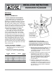
1. airFoil ProPeller and BuShingS
Sound Fighter Fans™ cast aluminum airfoil
propellers are furnished with split taper lock
bushings for mounting the propeller to the shaft.
When properly positioned, the bushing grips the
hub with a positive clamping action. The flange is
bolted to the fan hub to secure the fan, and when
the bolts are tightened, the tapered surface of the
split bushing is compressed around the shaft.
2. inStalling aSSeMBlY oF ShaFt
The first step in installing a tapered bushing
is to thoroughly clean the shaft, the bore and
exterior of the bushing, and the tapered bore
of the component. Nicks, burrs, dirt, and chips
should be removed, since they can cause a loss
of concentricity and even gripping strength. The
housing should be inserted into the hub with it’s
holes matched with the hub’s holes. The cap-
screws should be inserted in the holes that are
threaded on the hub side. The propeller should
then be mounted on the shaft, with the bushing in
place, and the capscrews tightened to the torque
values shown below.
3. noteS on CorreCt aSSeMBlY
A. Bushing barrel and bore of propeller are tapered
-this assures concentric mounting and a true
running propeller.
B. Capscrews, when tightened, lock bushing in
propeller. Use capscrews threaded full length.
BuShing diaMeter length torque
no. (Ft.lBS.)
H 1/4-20 1" 6
P 5/16-18 1-1/4" 13
Q 3/8-16 2" 2
SD 1/4-20 1" 6
SK 5/16-18 1-1/4" 13
Caution: MAKE SURE CAPSCREW
LENGTHS MATCH TRIANGLE ENGINEERING’S
RECOMMENDATIONS. SHORTER CAPSCREWS
FROM BUSHING MANUFACTURER ARE DESIGNED
FOR CAST IRON, NOT ALUMINUM.
C. Bushing is split so that when the locking capscrews
force the bushing into the tapered bore, the
bushing grips the shaft with a positive clamping fit
- this will withstand vibration and punishing loads
without being loosened.
D. Propeller and bushing assembly is keyed to shaft
and held in place by compression - this gives
added driving strength. The use of an optional
key for securing the bushing to the propeller hub
is generally not required, except on high speed,
high torque applications. Contact factory for
recommendations.
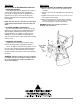
E. Propeller is easily removed from the shaft by
inserting and tightening two of the capscrews into
the tapped holes in the bushing flange - this forces
the bushing loose from the propeller and releases
the compression so that the entire assembly will
slide from the shaft.
Flanged tapered
bushing bolts to hub.
Extra bolt holes are
used to facilitate
removal. Flange should
not be hammered.