
User guide
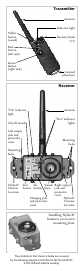


Transmitter Components:
•
Transmitter
•
Lanyard for transmitter
•
Short antenna for transmitter
•
9-volt alkaline battery (already installed)
•
Pro Control™ RL Owner’s Guide
Receiver Components:
•
Receiver
•
Long antenna for receiver
•
AC charger
•
Two Nylatch
®
fastener sets per receiver
•
Spare charging jack protection covers
•
Set of adhesive identification numbers
•
Pro Control™ RL Owner’s Guide
Accessories for the
Pro Control™ RL:
Order these accessories from your Tri-Tronics
dealer, on our web site, or by calling us at
1-800-456-4343:
•
Extension cord for receiver
•
Cordura
®
transmitter holster (spring clip style)
•
Cordura
®
transmitter holster (quick clip style)
Please note you may order a separate
receiver or transmitter for your Pro Control™
RL system at any time. Factory matching
of components is not needed, because the
Pro Control™ RL is field-settable!
Detailed Instructions
Antennas
The
short
antenna is for use with the
transmitter
.
The
long
antenna is for use with the receiver(s).
Installing the wrong antenna on each device
will reduce your range. Do not operate the
Pro Control™ RL without antennas in both
the transmitter
and
receivers.
Transmitter Dial
The transmitter has seven dial positions, numbered
1-7. Each dial position controls a different receiver.
It is possible to operate up to seven receivers with
one Pro Control™ RL transmitter. When using
several training devices, move the transmitter dial
to the next device to be activated, then activate it
with the appropriate transmitter button.
Receiver Jacks
The receiver has two output jacks so you can
operate two launchers, bird releasers, or other
compatible training devices from each receiver.
One jack is on the left side of the receiver; the
other is on the right side
. (Left and right as you
hold the receiver with the antenna pointing up
and the control switches facing you.)
The location of the left jack corresponds exactly
to the location of the output jack on our older
150 System receivers, so the Pro Control™ RL
receiver should be physically compatible with
any training device you have operated with
a 150 System.
Test Switch
Pressing the TEST switch on the receiver will
cause the lights next to the words “left” and
“right” to light up when a device is plugged into